
Device and method for quick online fault detection of high voltage thyristor valve block

A high-voltage thyristor valve, fault detection technology, applied in the direction of testing dielectric strength, circuit breaker testing, etc., can solve the problems of complex detection circuit structure, slow response speed, difficult to operate, etc. Fast, reliable results

Inactive Publication Date: 2015-01-07
HARBIN INST OF TECH
View PDF3 Cites 0 Cited by
  • Summary
  • Abstract
  • Description
  • Claims
  • Application Information

AI Technical Summary

Problems solved by technology

[0003] The purpose of the present invention is to solve the problems of complex structure, difficult operation, slow response speed and high cost of the current detection circuit for detecting high-voltage thyristor valve groups, and provide a fast online fault detection device and method for high-voltage thyristor valve groups

Method used


Image

  • Device and method for quick online fault detection of high voltage thyristor valve block
  • Device and method for quick online fault detection of high voltage thyristor valve block
  • Device and method for quick online fault detection of high voltage thyristor valve block

Examples


specific Embodiment approach 1

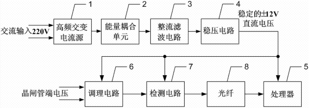
[0039] Specific implementation mode one: the following combination figure 1 with Image 6 Describe this embodiment, the high-voltage thyristor valve group fast online fault detection device described in this embodiment, it includes a high-frequency alternating current source 1, an energy coupling unit 2, a rectification filter circuit 3, a voltage stabilizing circuit 4, a processor 5, a conditioning Circuit 6, detection circuit 7 and optical fiber 8,

[0040] The output end of the high-frequency alternating current source 1 is connected to the input end of the energy coupling unit 2, the output end of the energy coupling unit 2 is connected to the AC input end of the rectification filter circuit 3, and the DC output end of the rectification filter circuit 3 is connected to the voltage stabilizing circuit 4 is connected to the input end, and the output end of the voltage stabilizing circuit 4 is connected to the DC power supply end of the processor 5, the conditioning circuit ...

specific Embodiment approach 2

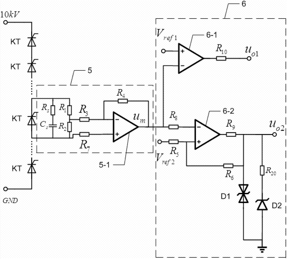
[0045] Specific implementation mode two: this implementation mode will further illustrate the first implementation mode, and the conditioning circuit 6 includes an amplifier 6-1, a resistor R 1 , resistance R 2 , resistance R 3 , resistance R 4 , resistance R 7 , resistance R S and capacitance C S ,

[0046] Resistance R S and capacitance C S Connect in parallel to both ends of the thyristor to be detected in the high-voltage thyristor valve group after being connected in series;

[0047] Resistance R 1 and resistor R 2 connected in parallel with resistor R S and capacitance C S Both ends of the series branch;

[0048] Resistance R 1 and resistor R 2 The junction point with the resistor R 3 Connected to one end of the resistor R 3 The other end of is connected with the inverting input end of amplifier 6-1;

[0049] Resistance R 1 and resistor R 2 The resistance R of the series branch 2 side with resistor R 7 Connected to one end of the resistor R 7 The ot...

specific Embodiment approach 3

[0051] Specific embodiment three: this embodiment will further illustrate embodiment one or two, the detection circuit 7 includes a single-limit comparator 7-1, a hysteresis comparator 7-2, a resistor R 5 , resistance R 6 , resistance R 8 , resistance R 9 , resistance R 10 , resistance R 20 , bidirectional Zener diode D1 and Zener diode D2,

[0052] The output terminal of the amplifier 6-1 is connected with the inverting input terminal of the single-limit comparator 7-1, and the non-inverting input terminal of the single-limit comparator 7-1 is connected with the reference voltage V ref1 , the output terminal of the single-limit comparator 7-1 and the resistor R 10 Connected to one end of the resistor R 10 The other end of the first monitoring voltage u o1 ;

[0053] The output of amplifier 6-1 is also connected with resistor R 8 Connected to one end of the resistor R 8 The other end of is connected with the inverting input end of hysteresis comparator 7-2,

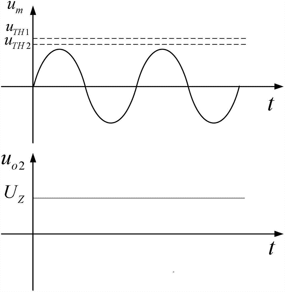
[0054]...


PUM


Abstract

A device and method for quick online fault detection of a high voltage thyristor valve block belongs to the field of online detection of thyristors and aims at resolving the problem that the existing detection circuit for detecting the high voltage thyristor valve block is complex in structure and high in cost. The device and method comprises a high frequency alternating current source, an energy coupling unit, a rectifying filtering circuit, a stabilizing circuit, a processor, a conditioning circuit, a detection circuit and an optical fiber. The output end of the high frequency alternating current source is connected with the input end of the energy coupling unit, the output end of the energy coupling unit is connected with the alternating current input end of the rectifying filtering circuit, the direct current output end of the rectifying filtering circuit is connected with the input end of the stabilizing circuit, the output end of the stabilizing circuit is simultaneously connected with the processor, the conditioning circuit and the direct current power supply end of the detection circuit, the conditioning circuit receives voltage signals of the thyristor end to be detected in the high voltage thyristor valve block, the output end of the conditioning circuit is connected with the input end of the detection circuit, and the output end of the detection circuit is connected with the signal input end of the processor through the optical fiber.

Description

technical field [0001] The invention relates to a fast on-line fault detection device and method for a high-voltage thyristor valve group, and belongs to the field of on-line detection of thyristors. Background technique [0002] In the field of high-voltage and high-current power electronics, it is often necessary to use multiple power semiconductor devices with lower withstand voltage levels in series to achieve a higher withstand voltage level for semiconductor switches. The cost of connecting multiple low-voltage power semiconductor switches in series is lower than using A single switching device with a high withstand voltage rating is low. In the series valve group work, the safe operation of the components in the group directly affects the reliability of the valve group work. Taking the thyristor as an example, due to the limitation of the withstand voltage level of the thyristor, in the medium and high voltage field, multiple thyristors must be used in series. Since...

Claims


Application Information

Patent Timeline
Patent Type & Authority Patents(China)
IPC IPC(8): G01R31/327G01R31/12
Inventor 高强徐殿国金淼鑫韩继强张巍李刚张鹏淼寇佳宝李晓璐
Owner HARBIN INST OF TECH
Learn More