
Thin-film capacitor structure for direct-current link circuits

A film capacitor and line technology, applied in the structural field of DC link line film capacitors, can solve problems such as complex and harsh environments, achieve good stability, good overcurrent and self-healing ability, and simple process

Inactive Publication Date: 2013-03-27
YANGZHOU KAIPU ELECTRONICS
View PDF0 Cites 0 Cited by
  • Summary
  • Abstract
  • Description
  • Claims
  • Application Information

AI Technical Summary

Problems solved by technology

However, the development and utilization of these two energy sources are mostly in remote areas with sparsely populated areas, and the environment is complex and harsh. Therefore, the capacitor as the core component of the converter also puts forward higher requirements that are different from general industrial applications.

Method used


Image

  • Thin-film capacitor structure for direct-current link circuits
  • Thin-film capacitor structure for direct-current link circuits
  • Thin-film capacitor structure for direct-current link circuits

Examples


Embodiment Construction

[0015] The present invention will be further described below in conjunction with accompanying drawing and specific embodiment:

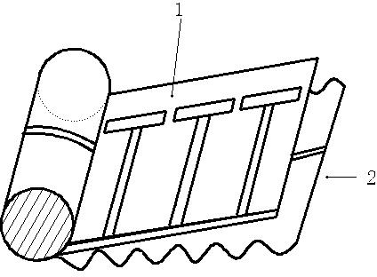
[0016] Such as figure 1 , 2 , Shown in 3: a kind of structure that is used for DC link line film capacitor, comprises bottom layer 1 and outer layer 2, and described bottom layer 1 is metallized T-type safety film with double side left, and described outer layer 2 is double side left side The width of the light film 3 at the edge of the double-sided metallized film is 3mm.


PUM


Abstract

The invention discloses a thin-film capacitor structure for direct-current link circuits. The thin-film capacitor structure comprises a bottom layer and an outer layer, wherein the bottom layer is a double-margin metalized T-shaped safety thin film, the outer layer is a middle-margin double-side metalized thin film, and the width of optical film at the margin of the middle-margin double-side metalized thin film is 3 mm. The thin-film capacitor structure is made of common raw materials and is compatible with existing thin-film capacitor processes, and capacitors of the structure have good over-current capacity and self-healing capacity and long service lives.

Description

[0001] technical field [0002] The invention relates to a high-voltage and large-capacity high-performance capacitor structure used for DC-Link (direct-current link) lines, in particular to a structure for film capacitors used in DC-link lines. Background technique [0003] In recent years, the petrochemical energy that supported the rapid development of human civilization in the 20th century, mainly oil, coal and natural gas, has experienced an unprecedented crisis. In addition to the continuous decline in its reserves, what is more serious is that scientific research has found that petrochemical energy after use After the carbon dioxide gas produced is emitted into the atmosphere as a greenhouse effect gas, it has artificially caused global warming, which has aroused people's widespread concern and thinking about the power source of future social development. The energy strategies of many countries have an obvious policy orientation—to encourage the development of new ene...

Claims


Application Information

Patent Timeline
Patent Type & Authority Applications(China)
IPC IPC(8): H01G4/33H01G4/005H01G4/06
Inventor 徐道安毛翔宇
Owner YANGZHOU KAIPU ELECTRONICS
Learn More