Magnetic sensor device

A technology of magnetic sensors and magnets, applied in measuring devices, instruments, measuring magnetic variables, etc., can solve the problems of detection sensitivity deviation, small variation, low detection sensitivity of magnetic patterns, etc., and achieve the effect of good sensitivity

Inactive Publication Date: 2013-03-27
MITSUBISHI ELECTRIC CORP
View PDF11 Cites 19 Cited by
  • Summary
  • Abstract
  • Description
  • Claims
  • Application Information

AI Technical Summary

Problems solved by technology

Therefore, there is a problem that the change amount of the resistance value of the magnetoresistance effect element is small, and the detection sensitivity of the magnetic pattern contained in the object to be sensed is low.
In addition, in the conventional magnetic sensor device, there is a problem that the detection sensitivity varies due to the assembly error of the magnetic sensor device or the deviation of the passage position of the object to be sensed.

Method used


Image

  • Magnetic sensor device
  • Magnetic sensor device
  • Magnetic sensor device

Examples


Embodiment approach 1

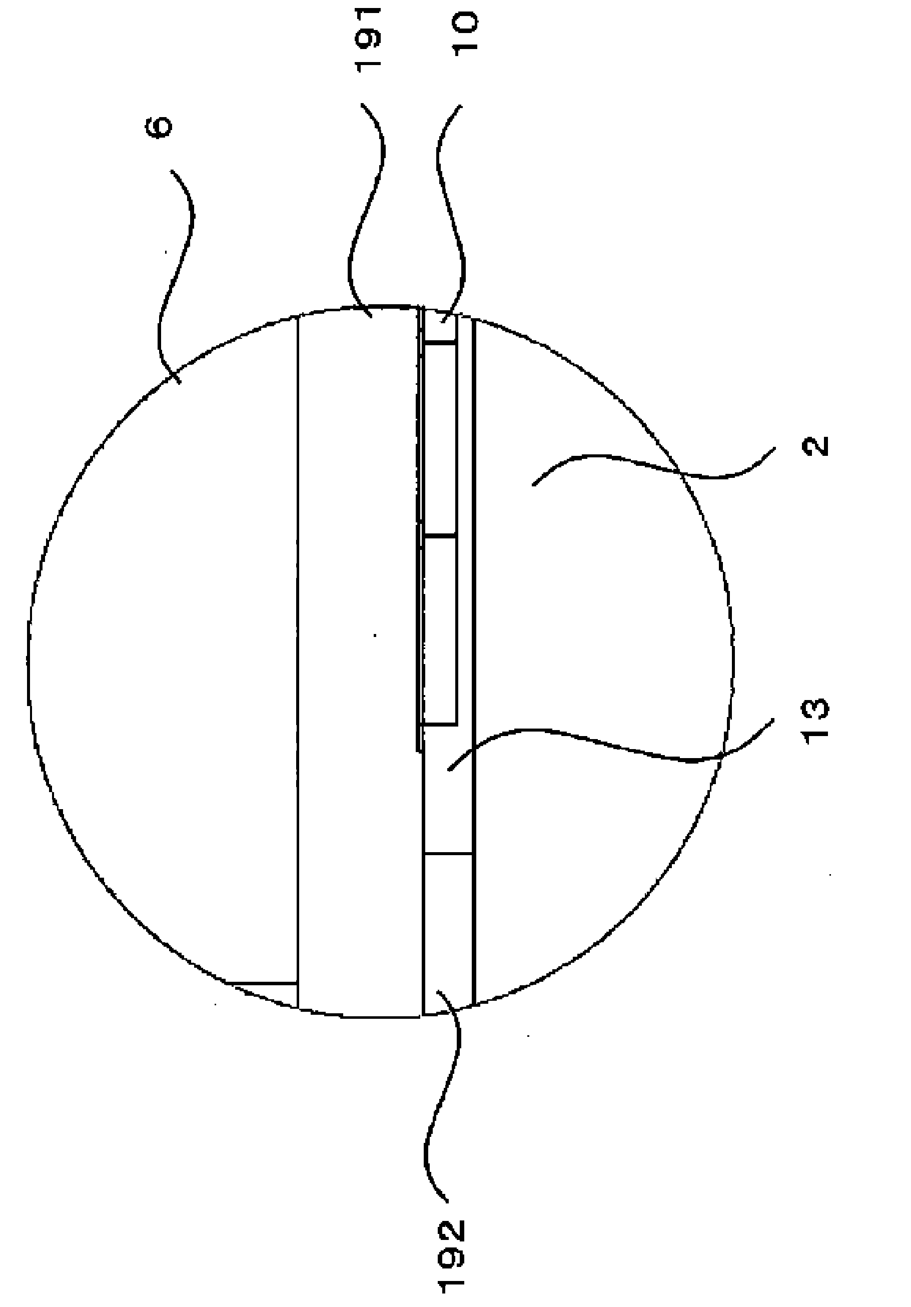
[0100] Below, refer to figure 1 with figure 2 The magnetic sensor device 201 according to Embodiment 1 of the present invention will be described. it's here, figure 1 It is a cross-sectional view of the magnetic sensor device 201 cut along a vertical plane parallel to the transport direction of the object to be detected (object to be sensed). figure 2 yes figure 1 A sectional view taken along line II-II of the magnetic sensor device 201 shown.

[0101] As shown in the figure, the magnetic sensor device 201 includes a housing 1 . The housing 1 is composed of an upper housing 1u and a lower housing 1s each in a rectangular state. The upper frame body 1u and the lower frame body 1s are made of, for example, a magnetic body or the like.

[0102]The hollow part 2 functioning as the conveyance path of the object to be sensed and a magnet accommodating part is formed in the inside of the upper frame 1u. A first slit 3 communicating with the hollow portion 2 is formed on one ...

Embodiment approach 2

[0133] Figure 11 It is a plan view showing the mounting state of the AMR element 10 viewed from the hollow portion 2 on the side of the multilayer substrate 9 of the magnetic sensor device 202 according to Embodiment 2 of the present invention. Figure 12 It is a schematic diagram showing the connection state of the AMR element 10 and the external circuit of the magnetic sensor device 202 according to Embodiment 2 of the present invention. exist Figure 11 with Figure 12 in, right with Figure 4 The same structural elements are attached with the same reference numerals, and descriptions thereof are omitted. exist Figure 11 Among them, the resistor pattern 102 a of the AMR element 10 is arranged such that the long sides of the rectangular shape extend in the direction perpendicular to the conveyance direction (X-axis direction), that is, the reading width direction (Y-axis direction). The resistor pattern 102c is arranged such that the long side of the rectangular shape...

Embodiment approach 3

[0139] Figure 14 It is a plan view showing the mounted state of the AMR element 10 viewed from the hollow portion 2 on the side of the multilayer substrate 9 of the linear magnetic sensor device 203 according to Embodiment 3 of the present invention. exist Figure 14 in, right with Figure 11 The same structural elements are attached with the same reference numerals, and descriptions thereof are omitted. In the in-line magnetic sensor device 203, the holes 9a of the multilayer substrate 9 are mounted in an array in the direction perpendicular to the transport direction (X-axis direction), that is, in the reading width direction (Y-axis direction). AMR element 10. The linear magnetic sensor device 203 performs the same operation as the magnetic sensor device 202 of the second embodiment. again, in Figure 14 In the example, as the resistor body pattern of the AMR element 10, use Figure 11 Resistor patterns 102a and 102b of Embodiment 2 are shown, but it is also possible...


PUM


Abstract

A first magnet (6) and a second magnet (7) arranged so that the opposite poles thereof face one another are provided in a wall surface of a hollow section (2) through which paper currency (5) is transported, and thereby form a gradient magnetic field including a zero point both in a magnetic field component in the direction in which the poles face one another between the magnets, and in a magnetic field component in the direction of transport of the paper currency (5) within the hollow section (2). An AMR element (10) is provided between the paper currency (5) and the first magnet (6). The AMR element (10) is enclosed in a multilayer substrate and is clad with a resin. The AMR element (10) is provided in a region of low magnetic field strength near where the magnetic field strength of the gradient magnetic field reaches the zero point in the transport direction. The paper currency (5) passes through a region of high magnetic field strength in the gradient magnetic field.

Description

technical field [0001] The present invention relates to a magnetic sensor device that detects minute magnetic patterns formed on objects to be sensed such as banknotes. Background technique [0002] The magnetic sensor device is used to detect minute magnetic patterns such as magnetic patterns formed on banknotes. Among the magnetic sensor devices, there is a magnetic sensor device using a magneto-resistive element having a characteristic that a resistance value changes according to the strength of an applied magnetic field. The remanent magnetization of the magnetic pattern included in the sheet-like medium such as banknotes is weak. Therefore, in order to detect the magnetic pattern, the magnetoresistance effect element must be placed in an environment with a strong magnetic field, and then the banknotes are transported near the magnetoresistance effect element. [0003] However, in the non-contact type magnetic sensor device, the object to be sensed and the magnetoresis...

Claims


Application Information

Patent Timeline
Patent Type & Authority Applications(China)
IPC IPC(8): G01R33/09G01R33/02
CPCG01R33/09G01R33/091G01R33/096G07D7/04G01R33/02
Inventor 尾込智和白花良治庄司俊明武舎武史井上甚冈田正明
Owner MITSUBISHI ELECTRIC CORP
Why Eureka
Try Eureka