Spine bolt

A technology of screw and spine, applied in the direction of internal fixator, internal bone synthesis, fixer, etc., can solve the problems of reducing the joint holding force of spinal screw and cancellous bone, reducing the strength of the screw body, and insufficient strength of spinal screw, etc., to achieve reduction The probability of surgical bleeding infection and other complications, the effect of increasing the intensity and increasing the lead

Inactive Publication Date: 2013-04-03
SUZHOU XINRONG BEST MEDICAL INSTR
View PDF3 Cites 1 Cited by
  • Summary
  • Abstract
  • Description
  • Claims
  • Application Information

AI Technical Summary

Problems solved by technology

The disadvantages of the spinal screw with the above structure are as follows: 1. Because it is a single-head thread, the pitch is relatively small, so the screw speed is slow, resulting in a relatively high probability of surgical bleeding, infection and other complications; 2. The thread on the screw body The depth of the thread is the same, and the human skeleton is hard and dense cortical bone and spongy loose cancellous bone from the outside to the inside. In order to have a better grip on the cancellous bone, the depth of the thread is usually set relatively deep Correspondingly, the diameter of the screw body itself is reduced, and the strength of the screw body is correspondingly reduced, which easily causes the spinal screw located in the cortical bone part to be easily bent and deformed due to insufficient strength; Reducing the depth of the thread will greatly reduce the combined holding force between the spinal screw located in the cancellous bone and the cancellous bone

Method used


Image

  • Spine bolt
  • Spine bolt
  • Spine bolt

Examples


Embodiment 1

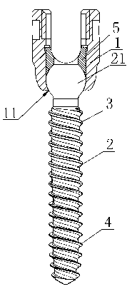
[0013] Embodiment 1: as figure 1 , image 3 As shown, the spinal screw described in this embodiment is a spinal polyaxial screw, including: a U-shaped nail seat 1, a screw body 2 is movably connected to the U-shaped nail seat 1, and the U-shaped nail seat 1 and the screw body in this embodiment The specific connection structure between 2 includes: the head of the screw body 2 is a spherical head 21, the bottom of the U-shaped nail seat 1 is provided with a through hole 11, and the U-shaped nail seat 1 above the through hole 11 is provided with a retaining sleeve 5 , the diameter of the through hole 11 is smaller than the diameter of the spherical head 21, and can ensure that the screw body 2 can protrude from the through hole 11, and the spherical head is formed between the bottom of the stop sleeve 5 and the U-shaped nail seat 1 above the through hole 11. part 21 of the spherical installation cavity, the spherical head 21 of the screw body 2 is installed in the spherical ins...

Embodiment 2

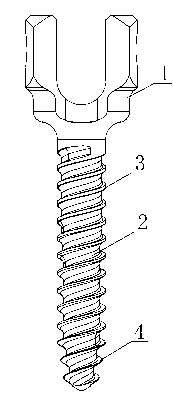
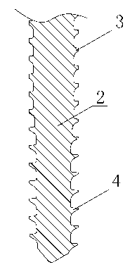
[0014] Embodiment 2: as figure 2 As shown, the spinal screw described in this embodiment is a spinal fixation screw, including: U-shaped nail seat 1, in this embodiment, the U-shaped nail seat 1 and the screw body 2 are of an integrated structure, and the screw body 2 is provided with threads. The thread is divided into upper and lower sections that are connected to each other. The upper thread is the cortical bone thread 3 located at the cortical bone segment, the lower thread is the cancellous bone thread 4 located at the cancellous bone segment, and the cortical bone thread 3 is connected to the cancellous bone segment. The outer diameters of the threads 4 are the same, but the inner diameter of the cortical bone thread 3 is greater than the inner diameter of the cancellous bone thread 4, so that the diameter of the screw body section located at the cortical bone part is greater than the diameter of the screw body section located at the cancellous bone part, and the cortica...


PUM


Abstract

The invention discloses a spine bolt which comprises a U-shaped bolt base on which a bolt main body is connected; an upper section of threads and a lower section of threads, which are connected with each other, are arranged on the bolt main body; the upper section of threads are cortical bone threads located at a cortical bone section; the lower section of threads are cancellous bone threads located at a cancellous bone section; the outer diameter of the cortical bone threads is the same with the outer diameter of the cancellous bone threads, and the inner diameter of the cortical bone threads is bigger than the inner diameter of the cancellous bone threads, so the diameter of the part of the bolt main body, which is located at the cortical bone part is bigger than the diameter of the part of the bolt main body, which is located at the cancellous bone part; and the cortical bone threads and the cancellous bone threads are both double threads. The spine bolt has the beneficial effects that flexural deformation of the spine bolt is effectively avoided, the bonding strength between the bolt main body and the bone of a human body is guaranteed, the nailing speed of the spine bolt is greatly improved, and the probabilities of surgical bleeding infection and the emergence of other complications are effectively reduced.

Description

technical field [0001] The invention relates to the field of medical instruments, in particular to a spinal screw used in orthopedic internal fixation surgery. Background technique [0002] Genetics, developmental abnormalities, trauma, chronic stress, as well as tumors and other diseases can lead to pathological conditions in the spine that reduce flexibility and limit the spine's range of motion. Adopting surgical internal fixation to treat the above-mentioned pathological conditions is a commonly used treatment method in medicine at present. Spinal screws are mostly used in anterior and posterior internal fixation operations of the thoracic spine, lumbar spine, lumbosacral spine, and iliac spine. Spinal screws include spinal polyaxial screws and spinal fixation screws. The structures of spinal polyaxial screws and spinal fixation screws are basically the same. , the thread is a single-start thread, and the depth of the thread on the screw body is consistent from top to ...

Claims


Application Information

Patent Timeline
Patent Type & Authority Applications(China)
IPC IPC(8): A61B17/86A61B17/70
Inventor 吴剑马鸿亮金桃
Owner SUZHOU XINRONG BEST MEDICAL INSTR
Why Eureka
Try Eureka