Femoral nail embedding reductor

A technology of reducer and bone marrow, which is applied in the field of medical devices, can solve the problems of aggravating the biological environment of the fracture end, traction, reset and maintenance instability, and poor accuracy, so as to reduce the damage to the biological environment, reduce surgical complications, and ensure surgical safety. sex increasing effect

Inactive Publication Date: 2013-04-03
SHANGHAI CITY PUDONG NEW AREA GONGLI HOSPITAL
View PDF7 Cites 6 Cited by
  • Summary
  • Abstract
  • Description
  • Claims
  • Application Information

AI Technical Summary

Problems solved by technology

[0004] 1. At present, the implantation and fixation of intramedullary nails are mostly done by hand under the supervision of X-ray fluoroscopy machine, which requires a lot of fluoroscopy, and both doctors and patients need to bear large doses of radiation damage;
[0005] 2. The traction reduction, reaming and intramedullary nail implantation in the operation can only be completed with the close cooperation of multiple people. The blindness is large and the accuracy is poor. If the reamer passes through the stump, it is easy to damage important nerves or Blood vessel;
[0006] 3. Traction, reduction and maintenance are unstable. In the process of maintaining the reduction state after the fracture end is reset, the redisplacement and deformation of the fracture end are prone to occur, and repeated traction and reduction are often required. Repeated reduction of the fracture end results in rounded ends Bluntness is an important factor leading to nonunion;
[0007] 4. Repeated reduction of the fracture end is easy to aggravate the destruction of the biological environment of the fracture end, which is an important factor leading to nonunion

Method used


Image

  • Femoral nail embedding reductor
  • Femoral nail embedding reductor
  • Femoral nail embedding reductor

Examples


Embodiment Construction

[0032] In the following description, many technical details are proposed in order to enable readers to better understand the application. However, those skilled in the art can understand that without these technical details and various changes and modifications based on the following implementation modes, the technical solution claimed in each claim of the present application can be realized.

[0033] In order to make the purpose, technical solution and advantages of the present invention clearer, the following will further describe the implementation of the present invention in detail in conjunction with the accompanying drawings.

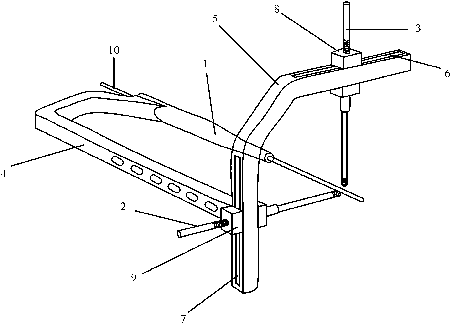
[0034] The first embodiment of the present invention relates to a femoral intramedullary nail implantation reducer. figure 1 It is a structural schematic diagram of the femoral intramedullary nail implanted reducer.

[0035] Specifically, as figure 1 As shown, the femoral intramedullary nail implantation reducer includes: a guide wire 10, a firs...


PUM


Abstract

The invention relates to the field of medical appliances, and discloses a femoral nail embedding reductor. According to the femoral nail embedding reductor, an intramedullary guidance device is arranged at a fracture near end; a lifting rod is arranged at a fracture remote end; intramedullary guidance is performed at the fracture near end; lifting reduction is performed through two lifting pins in sagittal view and coronal view at the fracture remote end; fracture three-dimensional reduction is performed through femora intramedullary guidance; the fracture near and remote ends can be accurately repositioned and temporarily fixed through simple fluoroscopy; and the femoral nail embedding reductor is convenient for intramedullary guide pins to be embedded and has high safety and accuracy. The femoral nail embedding reductor can be matched with the existing intramedullary nails for clinical use, and is simple to operate. Scales are formed on the lifting rod, the required lifting distance can be more accurately fixed during operation, and the femoral nail embedding reductor is accurate for reduction. The femoral nail embedding reductor breaks the traditional occlusion manual reduction, reduces the damage to the biological environment at the fracture ends, greatly enhances the operation safety, reduces operation complications, and can obviously reduce X-ray fluoroscopy amount and protect doctors and patients.

Description

technical field [0001] The invention relates to the field of medical instruments, in particular to the implantation reduction technique of a femoral intramedullary nail. Background technique [0002] Femoral shaft fracture is a relatively common limb fracture. At present, the treatment of limb fractures is nothing more than closed reduction plaster external fixation, external fixation bracket fixation, closed traction reduction and open traction reduction with plate or interlocking intramedullary nail fixation. method. However, in the treatment process of these methods, during the open reduction and internal fixation operation, when performing the reduction of the fracture end, the doctor first clamps the proximal and distal ends of the fracture with two rongeurs, and then holds the two ends with his hands. The bone clamp is used to reduce the fracture through the traction force of the arm. After the fracture is reduced, the force of the arm must be continued to maintain th...

Claims


Application Information

Patent Timeline
Patent Type & Authority Applications(China)
IPC IPC(8): A61B17/88A61B17/72
Inventor 杨铁毅
Owner SHANGHAI CITY PUDONG NEW AREA GONGLI HOSPITAL
Why Eureka
Try Eureka