
Discharge mechanism of wire harness winding machine

A technology of unloading mechanism and cantilever, which is applied in the field of unloading mechanism behind the wire handle of industrial electric detonator, which can solve the problems of easily damaged wire covering and unreliable unloading, etc. The effect of reliable materials, improving reliability and yield

Inactive Publication Date: 2013-04-03
中国兵器工业第二一三研究所
View PDF6 Cites 2 Cited by
  • Summary
  • Abstract
  • Description
  • Claims
  • Application Information

AI Technical Summary

Problems solved by technology

[0003] Aiming at the deficiencies of the prior art, the present invention provides a handle machine unloading mechanism with a simple structure, which effectively solves the problems of unreliable unloading from the handle machine and easy damage to the handle wire coating

Method used


Image

  • Discharge mechanism of wire harness winding machine

Examples


Embodiment Construction

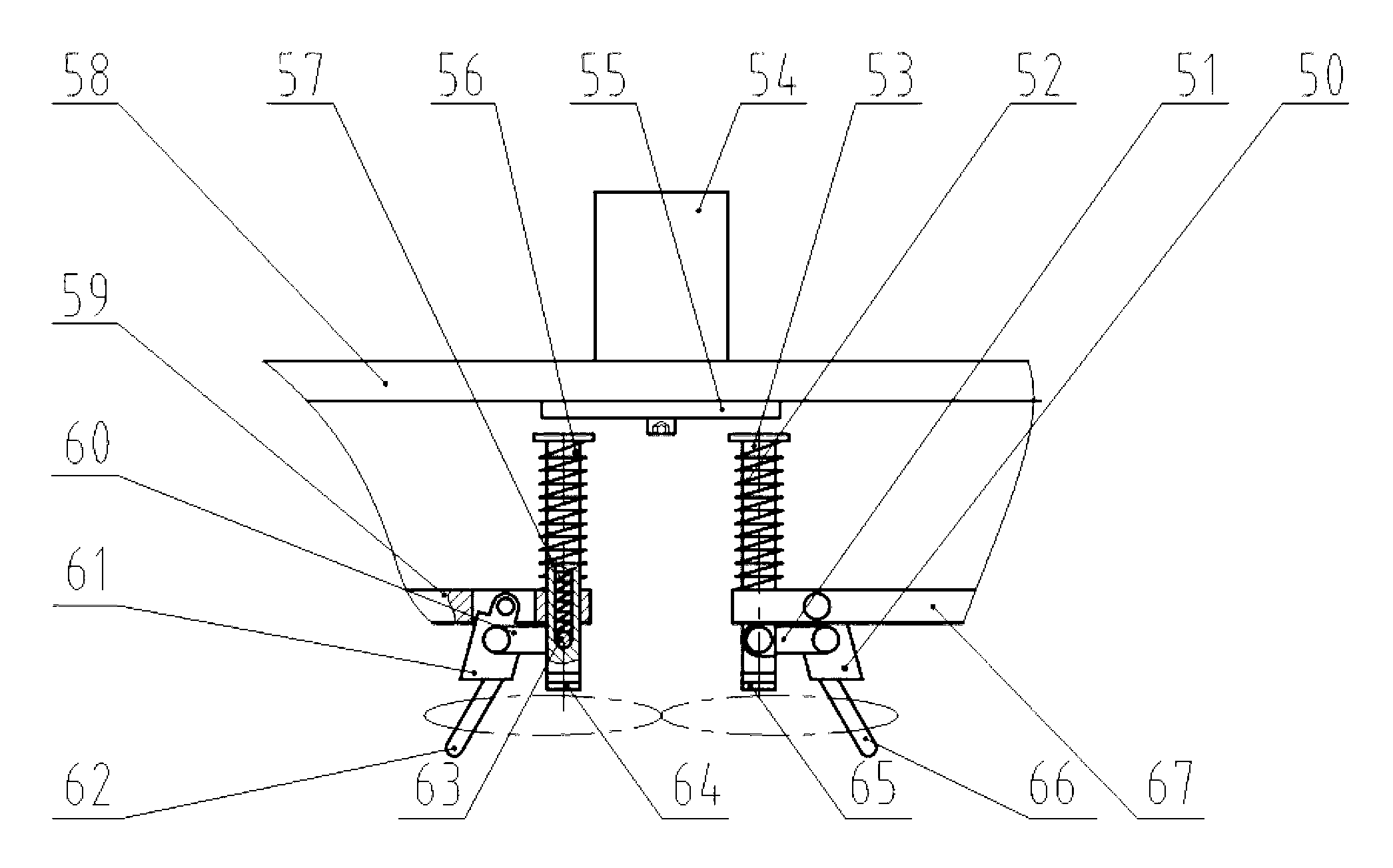
[0010] The invention provides an "8"-shaped handlebar unloading mechanism, which realizes product unloading through the movement of a cylinder and two plane four-bar mechanisms. First, use the cylinder to push the connecting rod of the connecting rod mechanism to move forward, and the connecting rod drives the handle head to loosen the two ends of the tensioned winding wire, and then the wound wire is removed through the action of the cylinder.

[0011] The handle machine discharge mechanism includes a handle base, a connecting rod, a discharge push shaft, a cylinder, a discharge push plate, a support plate, a cantilever, a handle base and a handle column.

[0012] The cylinder rod is connected with the unloading push plate, the unloading push shaft I and the unloading push shaft II can move linearly along the holes on the cantilever I and the cantilever II, the unloading push shaft I and the unloading push shaft II are connected with the cantilever I and the cantilever II A r...


PUM


Abstract

The invention provides a discharge mechanism of a wire harness winding machine. An air cylinder is mounted on a support plate; an air cylinder rod is connected with a discharge push plate; two cantilevers are symmetric about the cylinder rod and parallel to the support plate; two discharge push shafts are parallel to and symmetric about the cylinder rod and penetrate through the cantilevers to do rectilinear motion; return springs are mounted between the discharge push shafts and the cantilevers; strip-shaped holes are axially formed in the discharge push shafts; discharge push shaft inner shafts are mounted in the strip-shaped holes; limiting pressure springs are tightly propped against the discharge push shaft inner shafts; the discharge push shaft inner shafts are hinged with one ends of connecting rods; the other ends of the connecting rods are hinged with one ends of wire harness winding bases; the other ends of the wire harness winding bases are hinged with the cantilevers; the cantilevers, the discharge push shafts, the connecting rods and the wire harness winding bases respectively form two four-bar mechanisms and are bilaterally symmetric about the center of the discharge push plate; and an angular hole for fixing a wire harness winding column is formed in each wire harness winding base, so that an included angle is formed between the two wire harness winding columns. The discharge mechanism is simple and compact in structure and reliable in discharge, improves the discharge reliability and the yield, and further improves the winding efficiency of the wire harness winding machine.

Description

technical field [0001] The invention relates to a handle mechanism, in particular to an unloading mechanism behind the handle of an industrial electric detonator, which is used to unload the handle wire wound into an "8" shape from the handle post of the handle machine . Background technique [0002] The development of the handlebar machine has a history of many years, but how to reliably unload the handleable products has always been a technical problem that restricts the development of the handlebar machine to automation and intelligence. The wire has a certain tension during the winding process. After winding, the wire is tightly wound on the winding column, and the unloading mechanism directly pushes the wire to unload. If too much thrust is applied, the wire can be unloaded. However, it is easy to damage the covering of the handle wire. If the applied thrust is too small, the handle wire cannot be removed, and the unloading is unreliable, which will affect the normal o...

Claims


Application Information

Patent Timeline
IPC IPC(8): B65G47/82
Inventor 曹敏忠王锐王宪武郑文力宋国亮刘红利张明杨碧梅何博
Owner 中国兵器工业第二一三研究所
Learn More