SCS concrete filled steel tube pier reinforced by stirrup and stiffening rib at end

A technology of steel tube concrete and stiffeners, which is applied to bridges, bridge parts, bridge materials, etc., can solve the problems of easy bending at the upper and lower ends, small hoop effect, poor connection performance, etc., and achieve good torsional performance and construction The effect of low cost and convenient construction

Inactive Publication Date: 2015-06-24
CHANGAN UNIV
View PDF9 Cites 0 Cited by
  • Summary
  • Abstract
  • Description
  • Claims
  • Application Information

AI Technical Summary

Problems solved by technology

[0006] The technical problem to be solved by the present invention is to provide an SCS concrete-filled steel pipe pier whose ends are double-stiffened by stirrups and stiffening ribs in order to address the deficiencies in the above-mentioned prior art. Its structure is simple, its design is reasonable, its construction is convenient and its construction cost is low , Excellent mechanical properties, good use effect, can effectively solve the problems existing in the existing CFST piers, such as the poor connection performance between the outer steel pipe and the inner concrete, the outer steel pipe has little hoop effect on the inner concrete, and the upper and lower ends are prone to occurrence bending and other problems

Method used


Image

  • SCS concrete filled steel tube pier reinforced by stirrup and stiffening rib at end
  • SCS concrete filled steel tube pier reinforced by stirrup and stiffening rib at end
  • SCS concrete filled steel tube pier reinforced by stirrup and stiffening rib at end

Examples


Embodiment 1

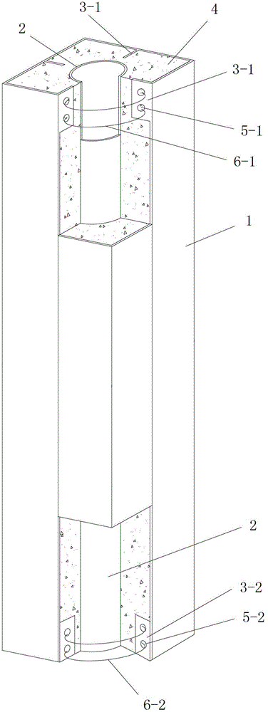
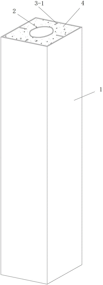
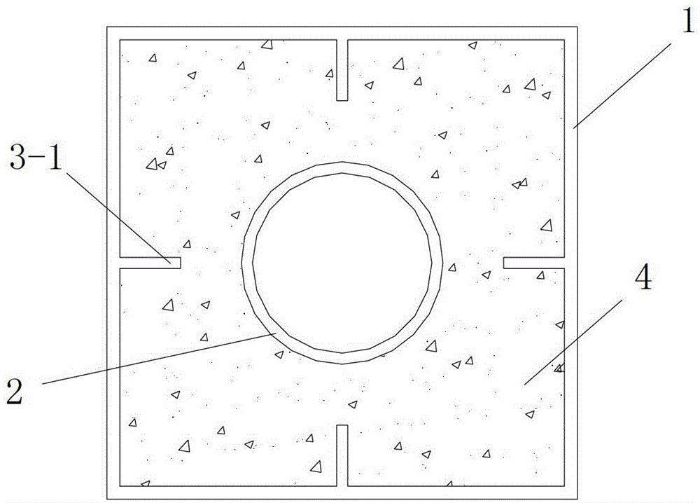
[0040] Such as figure 1 , figure 2 and image 3 As shown, the present invention includes an outer steel pipe 1, an inner steel pipe 2 sleeved inside the outer steel pipe 1, a top stiffening structure arranged between the top end of the outer steel pipe 1 and the top end of the inner steel pipe 2, and a top stiffening structure arranged between the bottom end of the outer steel pipe 1 and the inner steel pipe 2. The bottom stiffening structure between the bottom ends and the concrete structure 4 formed by pouring concrete in the cavity between the outer steel pipe 1 and the inner steel pipe 2 after the top stiffening structure and the bottom stiffening structure are laid out , the inner steel pipe 2 is a circular steel pipe and it is arranged in the inner middle part of the outer steel pipe 1 . The outer steel pipe 1 and the inner steel pipe 2 are arranged coaxially. The top stiffening structure includes multiple PBL stiffening ribs 1 3-1, and the bottom stiffening structur...

Embodiment 2

[0063] Such as Figure 4As shown, in this embodiment, the difference from Embodiment 1 is that the cross section of the outer steel pipe 1 is circular, A1:A2=1:0.6, and the wall thicknesses of the outer steel pipe 1 and the inner steel pipe 2 are both 25mm, A1=π·R 2 =10m 2 , where R is the outer diameter of the outer steel pipe 1.

[0064] In this embodiment, the structures and connections of other parts are the same as those in Embodiment 1.

Embodiment 3

[0066] Such as Figure 5 As shown, in this embodiment, the difference from Embodiment 2 is that the number of the first PBL stiffener 3-1 and the second PBL stiffener 3-2 is 6.

[0067] In this embodiment, the structures and connections of other parts are the same as those in Embodiment 2.


PUM

PropertyMeasurementUnit
thicknessaaaaaaaaaa
lengthaaaaaaaaaa
lengthaaaaaaaaaa

Abstract

The invention discloses an SCS concrete filled steel tube pier reinforced by a stirrup and a stiffening rib at an end, which comprises an outer steel tube, an inner steel tube sleeved in the outer sleeve tube, a top reinforcing structure, a bottom reinforcing structure and a concrete structured poured and formed by concrete in a cavity between the outer and inner steel tubes. The inner steel tube is circular. The inner and outer steel tubes are coaxially arranged. The top reinforcing structure comprises a plurality of PBL stiffening ribs I and a stirrup I arranged from top to bottom. The bottom reinforcing structure comprises a plurality of PBL stiffening ribs II and a stirrup II arranged from top to bottom. The transverse width of each PBL stiffening rib I and each PBL stiffening rib II is smaller than the distance between the outer and inner steel tubes arranged at the position. The SCS concrete filled steel tube pier reinforced by the stirrup and the stiffening rib at the end is simple in structure, reasonable in design, convenient to construct, lower in construction cost, excellent in mechanical performance and good in using effect, and various problems of current concrete filled steel tube piers can be effectively solved.

Description

technical field [0001] The invention relates to a steel pipe concrete bridge pier, in particular to an SCS steel pipe concrete bridge pier whose ends are double-stiffened by stirrups and stiffeners. Background technique [0002] Concrete filled steel pipe refers to the structure formed after the steel pipe is filled with concrete. The two materials of steel and concrete make up for each other's weaknesses and give full play to each other's strengths, so that the steel tube concrete has a high bearing capacity and excellent mechanical properties. Nowadays, CFST structures are more and more widely used in structures such as offshore platforms and long-span, heavy-duty, and light bridges, and the CFST structures used mainly have three cross-sectional forms: circular, square, and rectangular. However, the currently used concrete-filled steel tube structures generally have structural defects that limit the development and application of concrete-filled steel tube structures to a...

Claims


Application Information

Patent Timeline
Patent Type & Authority Patents(China)
IPC IPC(8): E01D19/02E01D101/24E01D101/30
Inventor 刘永健王旭高小育杨光辉刘世忠徐兵张俊光李娜宋瑶
Owner CHANGAN UNIV
Why Eureka
Try Eureka