Check patentability & draft patents in minutes with Patsnap Eureka AI!

Piezoelectric wafer self-energy supplying hydraulic damper

A hydraulic damper, chip-type technology, applied in the direction of piezoelectric effect/electrostrictive or magnetostrictive motors, shock absorbers, shock absorbers, etc., can solve the problem of low reliability and achieve high reliability Effect

Active Publication Date: 2013-04-03
ZHEJIANG NORMAL UNIVERSITY +2
View PDF8 Cites 2 Cited by
  • Summary
  • Abstract
  • Description
  • Claims
  • Application Information

AI Technical Summary

Problems solved by technology

[0004] The invention provides a piezoelectric chip type self-powered hydraulic damper to solve the problem of low reliability existing in existing piezoelectric hydraulic dampers and piezoelectric stacked self-powered adjustable hydraulic dampers

Method used


Image

  • Piezoelectric wafer self-energy supplying hydraulic damper
  • Piezoelectric wafer self-energy supplying hydraulic damper
  • Piezoelectric wafer self-energy supplying hydraulic damper

Examples


Embodiment Construction

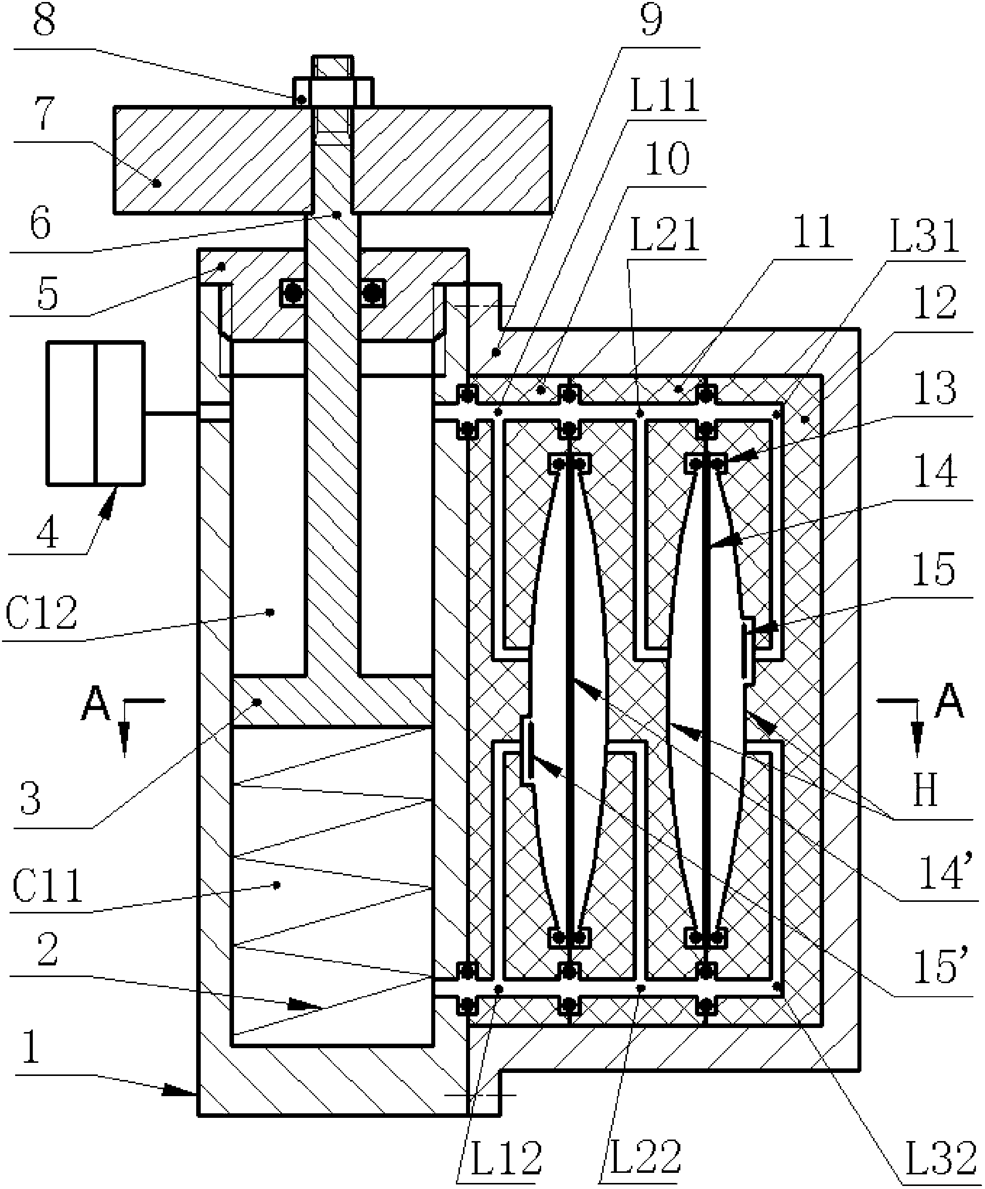
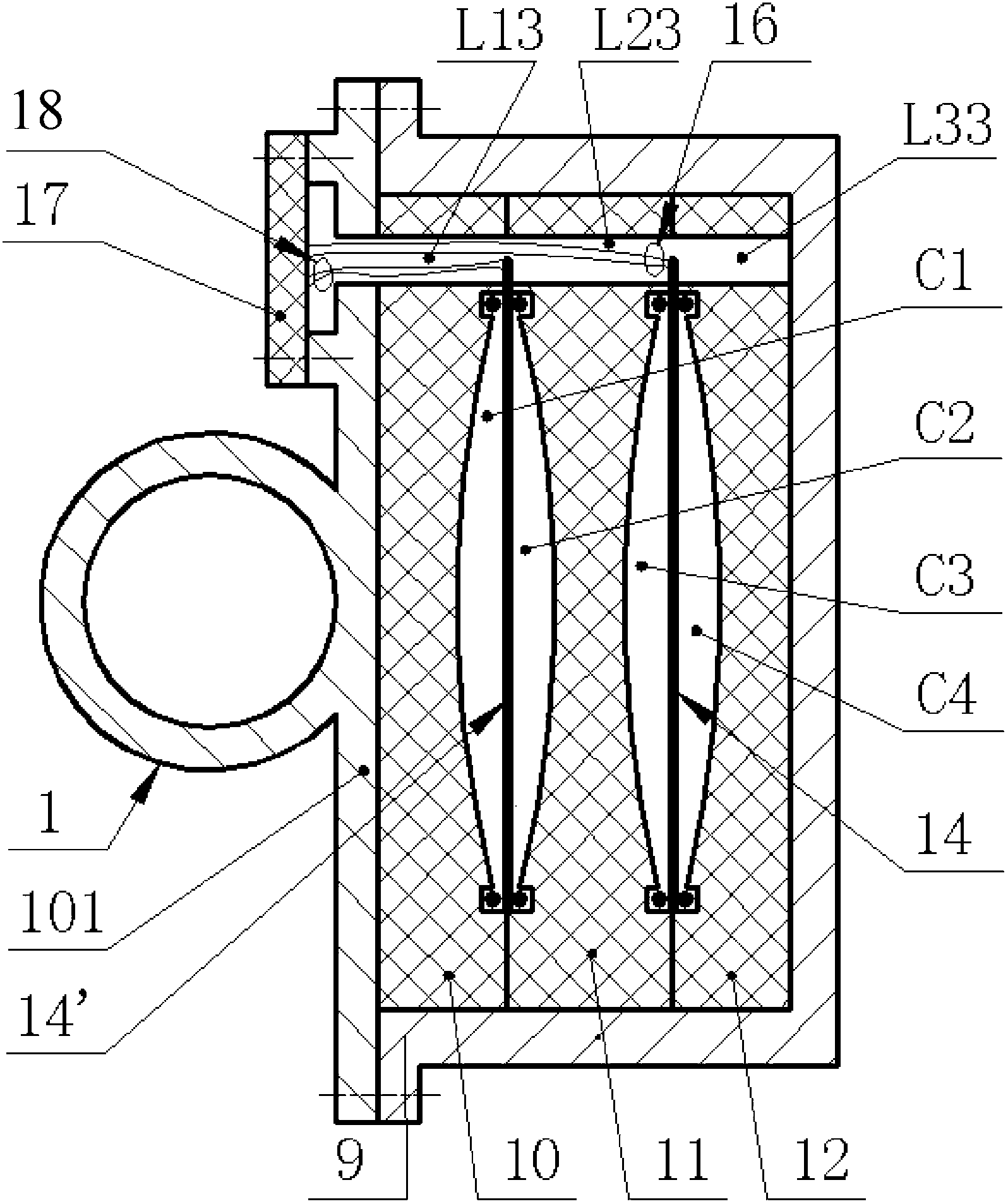
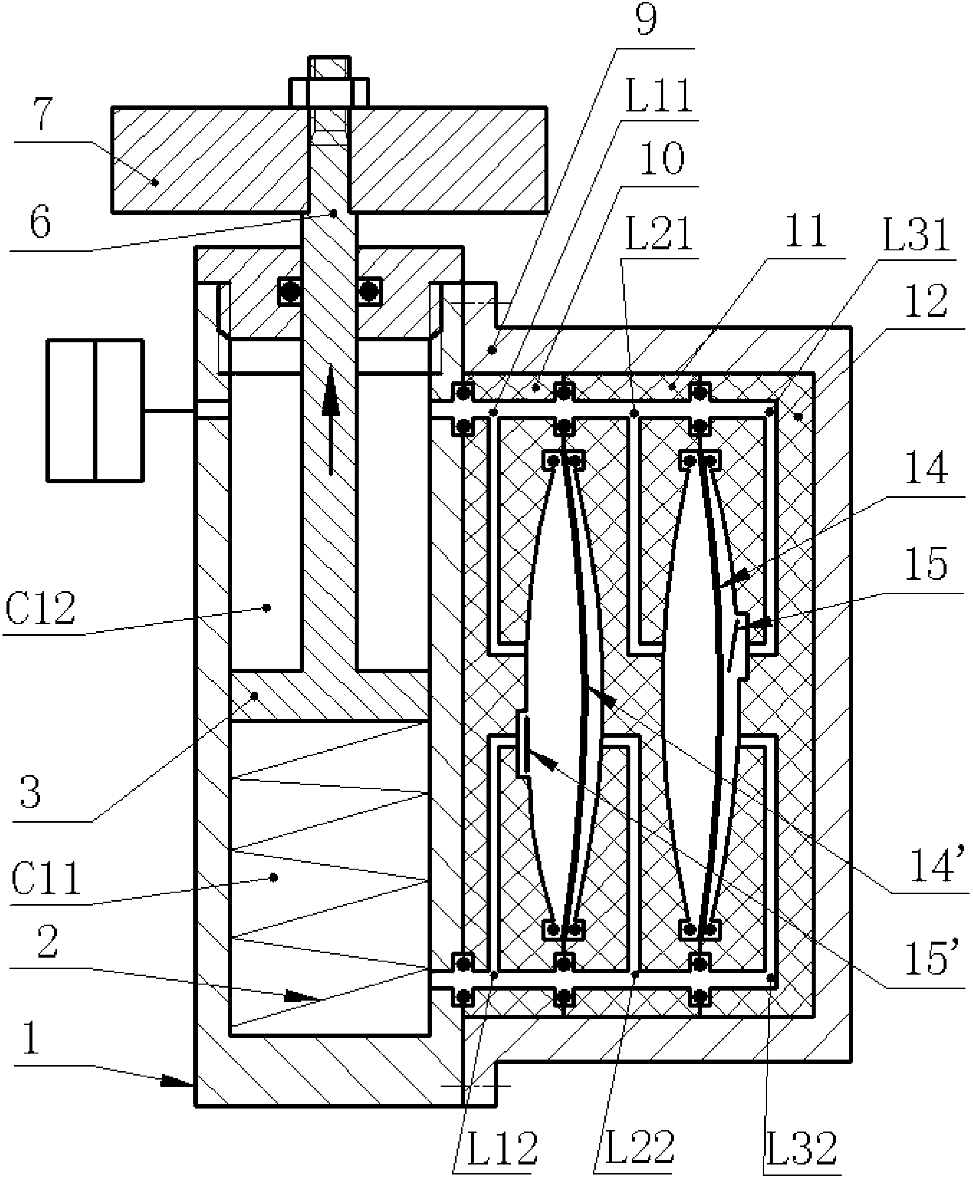
[0017] The cylinder head 5 is installed on the upper end of the cylinder body 1 through threads, the spring 2 is crimped in the lower chamber C11 of the cylinder body 1 through the piston 3, the vibration body 7 is fixed on the piston rod 6 through the nut 8, and the accumulator 4 is connected to the cylinder body through the pipeline. The upper cavity C12 of the body 1 is connected, and the housing 9 is installed on the connecting plate 101 on the outer wall of the cylinder body 1 through screws; Inside the casing 9; one side of the front pressing block 10 and the rear pressing block 12, and both sides of the middle pressing block 11 are provided with limiting curved surfaces H; between the front pressing block 10 and the middle pressing block 11, in the middle The first piezoelectric vibrator 14' and the second piezoelectric vibrator 14, which are formed by bonding the metal substrate 141 and the piezoelectric chip 142, are crimped between the pressing block 11 and the rear p...


PUM


Abstract

The invention relates to a piezoelectric wafer self-energy supplying hydraulic damper which belongs to an absorber. A cylinder cover is installed at the upper end of a cylinder body, a spring is pressed in a lower cavity of the cylinder body through a piston, a vibrating body is fixedly arranged on the piston rod, and an energy storage device is communicated with an upper cavity of the cylinder body. A front press block, a middle press block and a rear press block provided with limiting curved surfaces are sequentially pressed in a shell through a connecting plate installed on the outer wall of the cylinder body. Piezoelectric vibrators are respectively pressed between adjacent press blocks. Each limiting chamber and each damping chamber are communicated with the upper or lower cavity of the cylinder body through passageways on adjacent press blocks. Each damping chamber is internally provided with a one-way valve. The piezoelectric wafer self-energy supplying hydraulic damper provided by the invention has the advantages that the deforming shapes of the piezoelectric vibrators are controlled by the limiting curved surfaces, and the piezoelectric vibrators subjected to backpressure of the system on both sides in a non-working state do not bend or deform, so that the piezoelectric wafer self-energy supplying hydraulic damper is high in reliability, and stronger in power generating capacity and damp adjusting capacity.

Description

technical field [0001] The invention belongs to a shock absorber applied in the technical field of vibration control, and in particular relates to a hydraulic shock absorber that generates electricity and adjusts damping based on a piezoelectric chip, referred to as a piezoelectric chip self-powered hydraulic damper. Background technique [0002] Hydraulic dampers have been widely used in the field of vibration control of vehicles and mechanical equipment. The early passive hydraulic dampers were simple in structure, low in cost, and relatively mature in technology, but because the damping was not adjustable, their damping effect and environmental adaptability were poor, and they were not suitable for some occasions that required better vibration control effects, such as automobile engines. And frame suspension, vibration reduction of large precision instruments and equipment, etc. Therefore, people have proposed active and semi-active adjustable hydraulic dampers, that is,...

Claims


Application Information

Patent Timeline
IPC IPC(8): F16F13/00H02N2/00
Inventor 陈宇航阚君武王淑云曾平程光明
Owner ZHEJIANG NORMAL UNIVERSITY
Features
  • R&D
  • Intellectual Property
  • Life Sciences
  • Materials
  • Tech Scout
  • Unparalleled Data Quality
  • Higher Quality Content
  • 60% Fewer Hallucinations
Learn More