Combined with the window, the horizontal unit heat rejection air conditioner
An air-conditioning device and combined technology, which is applied to air-conditioning systems, windows/doors, heating methods, etc., can solve the problems of high energy consumption of air-conditioning, achieve the effects of blocking solar radiation, reducing indoor loads, and facilitating building structure coordination
- Summary
- Abstract
- Description
- Claims
- Application Information
AI Technical Summary
Problems solved by technology
Method used
Image
Examples
Embodiment 1
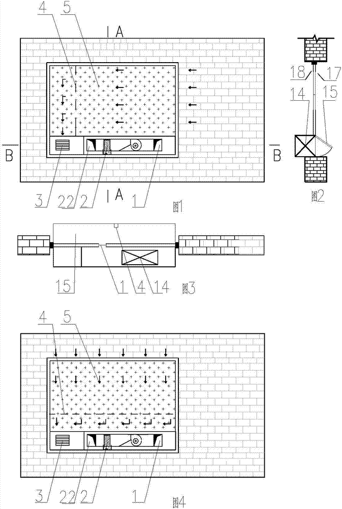
[0060] as attached figure 1 , 2 , 3, the window 20 is installed in the window opening of the building envelope of the horizontal unit heat exhaust air conditioning device combined with the window, and there is no less than one window type heat preservation device 15 inside the window 20 that can be opened or closed The horizontal air handling unit 14 is installed and the connection between other window sashes and window frames is mutually sealed, and the fresh air outlet 1 of the horizontal air handling unit 14 leads to the outside, and the air outlet 22 of the horizontal air handling unit 14 is connected to the indoor 18 are connected; the horizontal air handling unit 14 has an air exhaust outlet that communicates with the outside; there is an inner isolation device 5 on the inside of the window 20, and there is a diversion belt hole support device 4 between the inner isolation device 5 and the window 20. Between the inner isolation device 5 and the window 20, there is n...
Embodiment 2
[0063] as attached Figure 4 As shown, the difference between embodiment 2 and embodiment 1 is that: the diversion belt hole support device 4 of embodiment 2 is horizontal, and the indoor exhaust air enters the inner isolation from the air inlet on the right side of the inner isolation device 5 The air flow channel formed by device 5 , diversion belt hole support device 4 and window 20 is an exhaust air cavity, which takes away part of the heat load of window 20 and then exhausts it to the outdoor 17 through the exhaust fan 3 arranged at the air exhaust port.
Embodiment 3
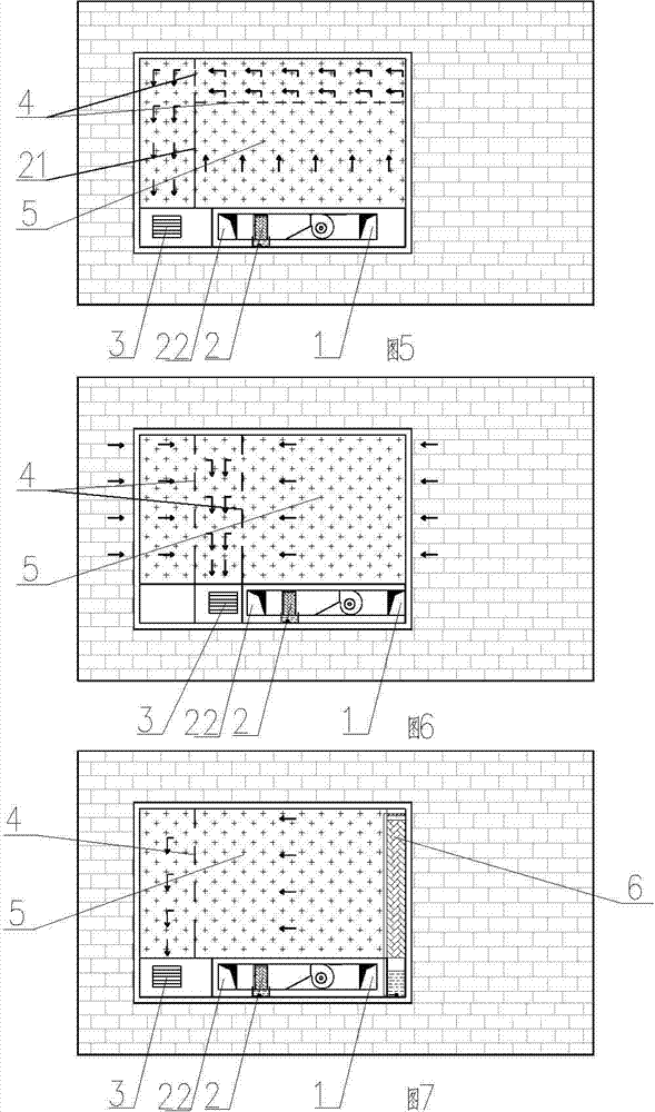
[0065] as attached Figure 5 As shown, the difference between embodiment 3 and embodiment 1 and embodiment 2 is that: between the inner isolation device 5 and the window 20 of embodiment 3, there are at least one deflector support plate 21 and two deflector belts The hole support device 4, the flow guide support plate 21 is vertical, one of the two flow guide belt hole support devices 4 is vertical and the other is horizontal, so that the indoor exhaust air from the inner isolation device 5 The air inlet on the lower side enters the inner isolation device 5, the air flow channel formed by the diversion belt hole support device 4 and the window 20 is an exhaust cavity (U-shaped exhaust cavity), which takes away part of the heat load of the window 20 , and then discharged to the outdoor 17 by the exhaust fan 3 arranged at the air outlet.
PUM
 Abstract
Description
Claims
Application Information
 - R&D
- Intellectual Property
- Life Sciences
- Materials
- Tech Scout
- Unparalleled Data Quality
- Higher Quality Content
- 60% Fewer Hallucinations
Browse by: Latest US Patents, China's latest patents, Technical Efficacy Thesaurus, Application Domain, Technology Topic, Popular Technical Reports.
© 2025 PatSnap. All rights reserved.Legal|Privacy policy|Modern Slavery Act Transparency Statement|Sitemap|About US| Contact US: help@patsnap.com


