
Heat pump dehumidifier

A dehumidifier and heat pump technology, applied in the field of dehumidifiers with heat pump heating function, can solve the problems of high failure rate, dehumidification, heat pump heating functions cannot be realized at the same time, complex air conditioning system, etc.

Active Publication Date: 2013-04-03
江苏高科应用科学研究所有限公司
View PDF7 Cites 6 Cited by
  • Summary
  • Abstract
  • Description
  • Claims
  • Application Information

AI Technical Summary

Problems solved by technology

In civil air defense, national defense, swimming pools and other occasions, the humidity load is large, especially in summer, the general air conditioner cannot meet the dehumidification requirements, and a dehumidifier is required; in winter, especially in the northern and western regions, the fresh air is dry and the temperature is low, so the air conditioning system is no longer needed Dehumidification or the amount of dehumidification needs to be small, and heating is required at the same time. Ordinary dehumidifiers, temperature-adjusting dehumidifiers, etc. cannot meet the heating requirements, and an air conditioning system is required.
If it is equipped with a dehumidifier and a heat pump air conditioner at the same time, the air conditioning system is complicated and the initial investment is large; the ordinary dehumidifier with heat pump function uses a four-way reversing valve to realize the reversing cycle of the refrigeration system, the refrigeration system is complicated, the failure rate is high, and the dehumidification , The heat pump heating function cannot be realized at the same time

Method used


Image

  • Heat pump dehumidifier
  • Heat pump dehumidifier
  • Heat pump dehumidifier

Examples


Embodiment 1

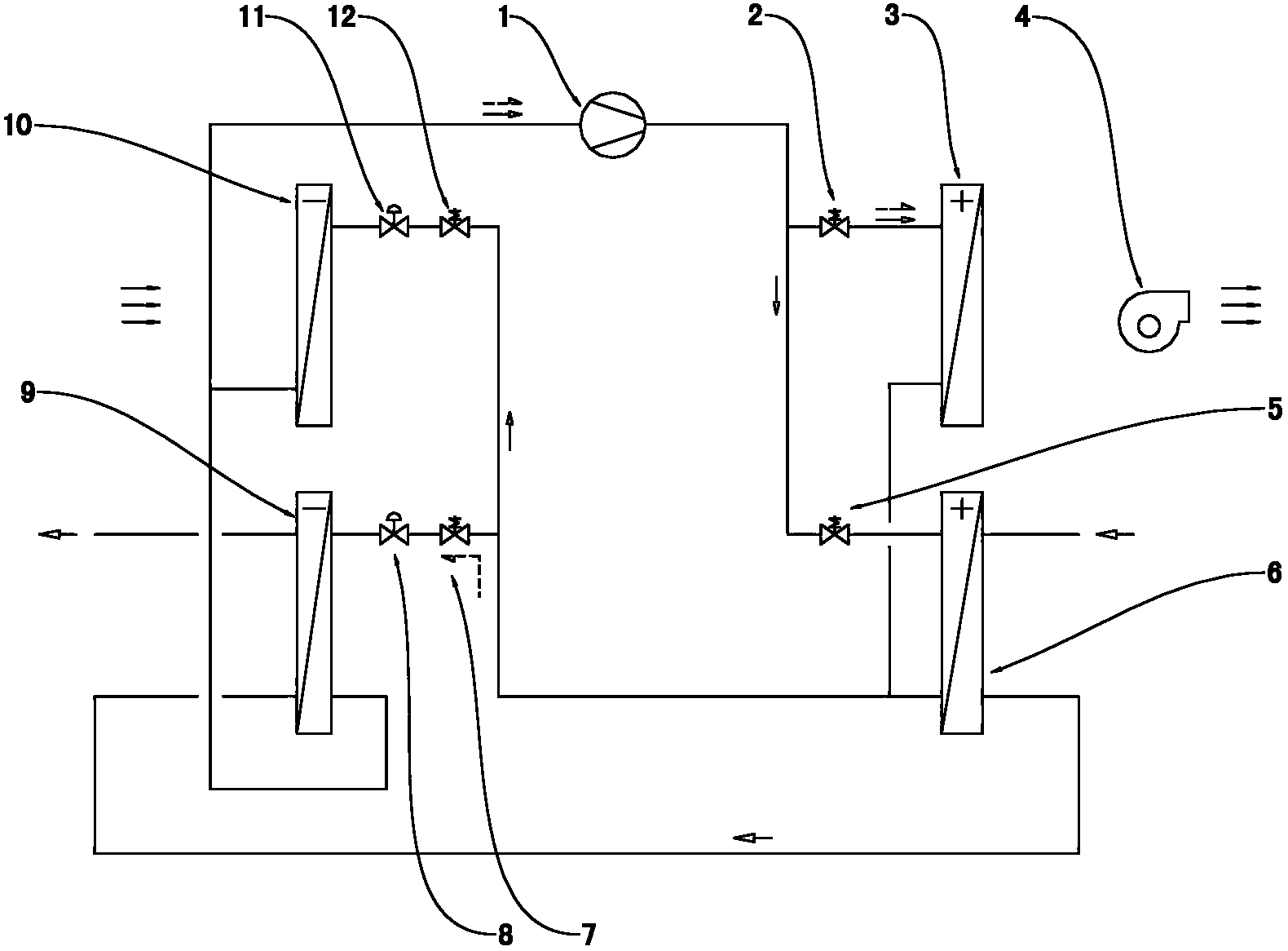
[0023] Example 1, please refer to figure 1 , The present invention is a heat pump dehumidifier, which includes an air handling system, a refrigerant circulation system, and a cooling water circulation system.

[0024] The air treatment system is located in the processing air duct of the unit, including the second evaporator 10, the first condenser 3, and the blower 4; when the dehumidification mode is working, the air to be treated passes through the second evaporator 10 and is cooled to below the dew point. The water vapor in the air is condensed and separated, and then heated by the first condenser 3, the temperature rises, and the relative humidity of the air decreases, and the treated air is sent into the air-conditioned room by the blower 4. When the heat pump heating mode works, the second evaporator 10 does not work, the air to be processed passes through the first condenser 3, is heated, and the temperature rises, and the processed air is sent into the air-conditioned...

example 2

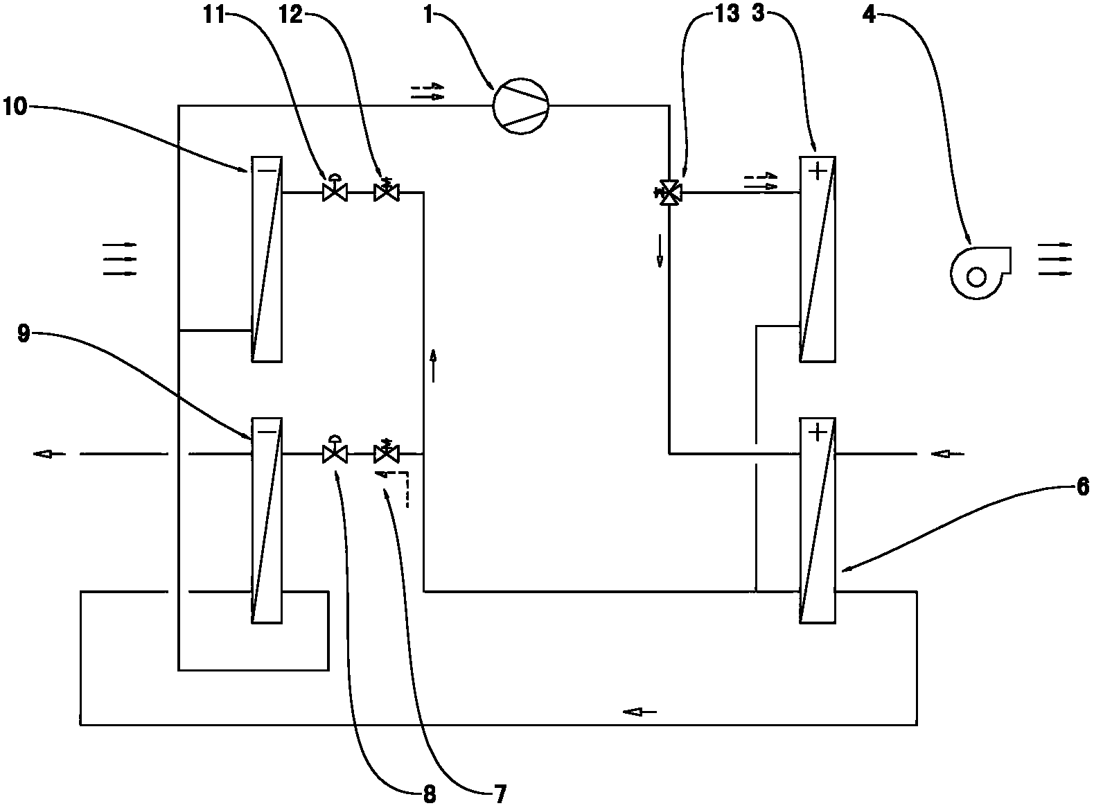
[0030] Example 2: Please refer to figure 2 , replace the first solenoid valve 2 and the second solenoid valve 5 with a three-way solenoid valve 13, the outlet of the compressor 1 is connected to the three-way solenoid valve 13, and the outlet of the three-way solenoid valve 13 is connected to the first condenser 3 and the second condenser at the same time 6. Compared with Embodiment 1, the three-way solenoid valve 13 is powered off, the compressor 1 is connected to the first condenser 3; the three-way solenoid valve 13 is powered on, the compressor 1 is connected to the second condenser 6, and the system control is simpler .

example 3

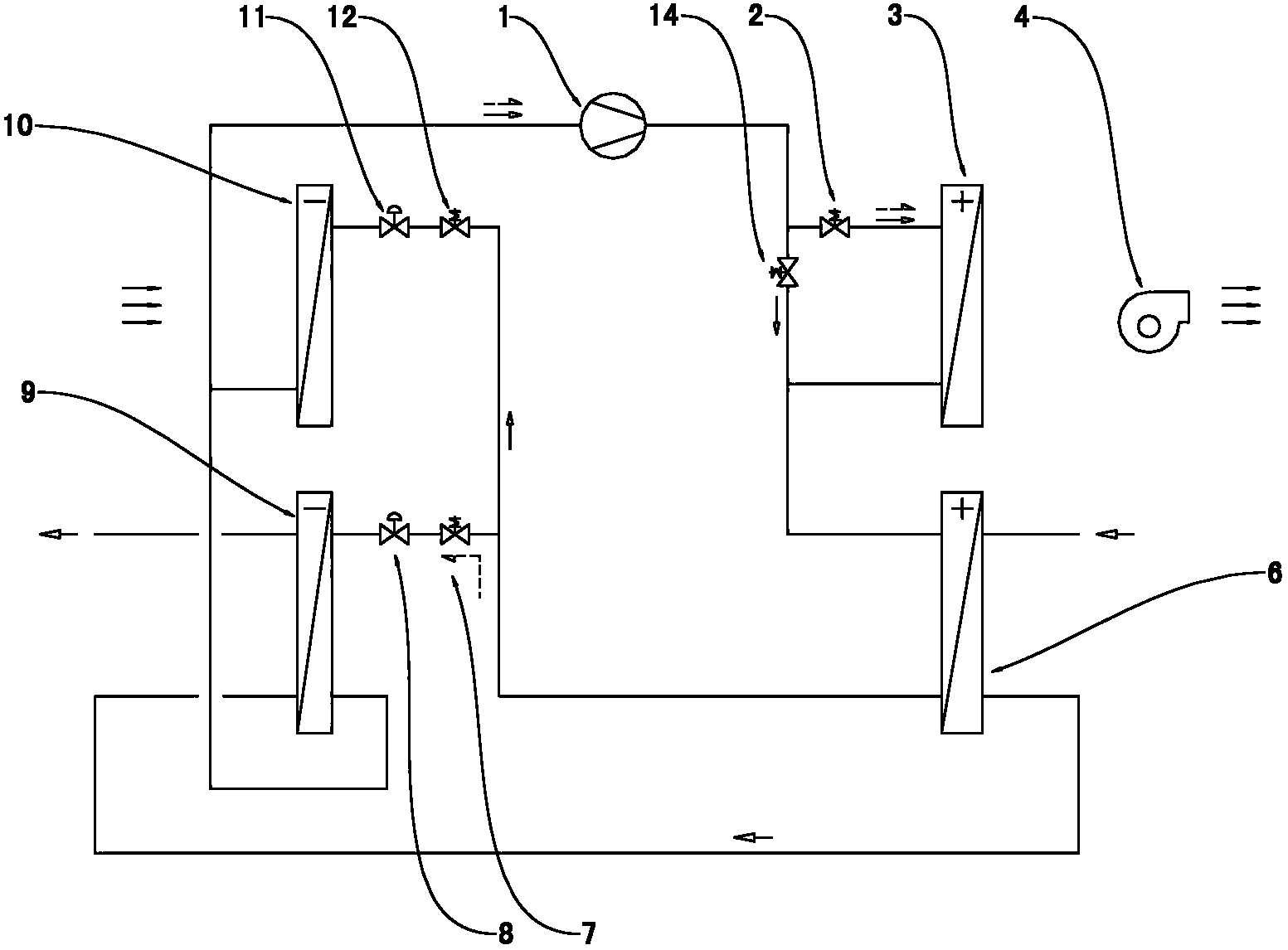
[0031] Example three: see image 3 The compressor 1 outlet of the refrigeration cycle system is connected to the first solenoid valve 2 and the fifth solenoid valve 14 at the same time, the first solenoid valve 2 is connected to the inlet of the first condenser 3, the fifth solenoid valve 14 is connected to the outlet of the first condenser Connect the inlet of the second condenser 6 after parallel connection;

[0032] When the dehumidification mode is working, the high-temperature and high-pressure gas discharged from the compressor 1 enters the first condenser 3 through the first solenoid valve 2, and part of the heat is transferred to the air outside the first condenser 3, and then passes through the second condenser 6 to convert Part of the heat is transferred to the cooling water, which is condensed into a liquid at high pressure and normal temperature; in this way, the temperature of the outlet air is moderate, and it is suitable for more occasions.

[0033] Compared wi...


PUM


Abstract

The invention relates to a heat pump dehumidifier which comprises an air treatment system, a refrigerant circulating system and a cooling water circulating system, wherein the air treatment system comprises a second evaporator, a first condenser and a blower passed by air required to be processed; the refrigerant circulating system adopts the structure that a compressor outlet is connected with the first condenser and a second condenser, which are connected with each other in parallel; a compressor inlet is connected with a first evaporator and the second evaporator, which are connected with each other in parallel; after being connected in parallel, the first condenser and the second condenser are connected with the first evaporator and the second evaporator, which are connected with each other in parallel; the refrigerant circulating system correspondingly comprises a solenoid valve, an expansion valve and the like connected with one another in parallel; the flowing direction of a refrigerant is changed through the solenoid valve to realize switching between refrigerating circulation and heat pump heating circulation; and the cooling water circulating system comprises the second condenser and the first evaporator passed by cooling water in sequence. The heat pump dehumidifier has the beneficial effects that the heat pump dehumidifier not only has a dehumidification function, but also has a heating function of a heat pump; and meanwhile, the switching between a dehumidification refrigerating circulation and a heat pump heating circulation can be realized without a four-way reversing valve.

Description

[0001] technical field [0002] The invention relates to a dehumidifier, in particular to a dehumidifier with a heat pump heating function. [0003] Background technique [0004] The purpose of building air conditioning is to discharge indoor waste heat and humidity outside and provide fresh air that meets hygienic requirements. The loads of the air conditioning system include: indoor cooling load, indoor humidity load, fresh air cooling load, and fresh air humidity load. In civil air defense, national defense, swimming pools and other occasions, the humidity load is large, especially in summer, the general air conditioner cannot meet the dehumidification requirements, and a dehumidifier is required; in winter, especially in the northern and western regions, the fresh air is dry and the temperature is low, so the air conditioning system is no longer needed Dehumidification or dehumidification needs to be very small, and heating is required at the same time. Ordinary dehum...

Claims


Application Information

Patent Timeline
Patent Type & Authority Applications(China)
IPC IPC(8): F25B29/00F25B41/04
Inventor 姚永明倪庆海
Owner 江苏高科应用科学研究所有限公司
Learn More