Refrigerant pipeline and heat exchanger provided with same

A technology of refrigerant tubes and heat exchangers, applied in refrigerators, refrigeration components, refrigeration and liquefaction, etc., can solve problems such as low efficiency, difficult water temperature control, and multiple functions, and achieve sufficient heat exchange and good shunting effects

Active Publication Date: 2015-04-29
CLIMAVENETA CHATUNION REFRIGERATION EQUIP SHANGHAI
View PDF7 Cites 0 Cited by
  • Summary
  • Abstract
  • Description
  • Claims
  • Application Information

AI Technical Summary

Problems solved by technology

Such systems typically limit and operate based on the discharge temperature of the compressor
Ejection cooling has several disadvantages: limited operating range of the compressor, inefficiency, etc.
For the heat recovery unit, it is very difficult to control the water-cooled oil cooling system, because the heat recovery unit itself is relatively complicated and has many functions, and it is difficult to control the water temperature, etc.

Method used


Image

  • Refrigerant pipeline and heat exchanger provided with same
  • Refrigerant pipeline and heat exchanger provided with same

Examples


Embodiment Construction

[0024] Several embodiments of the present invention are discussed in detail below with reference to the accompanying drawings.

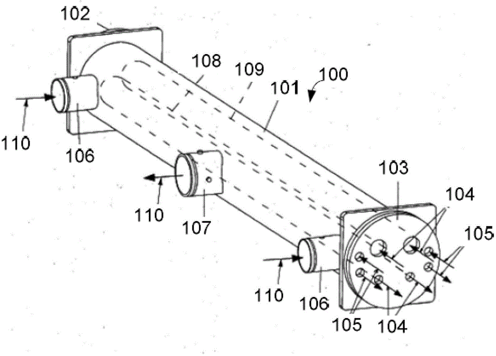
[0025] figure 1 The basic structure of the heat exchanger 100 of the present invention is schematically shown. As shown in the figure, the heat exchanger 100 of the present invention mainly includes: a tube wall 101, a first end 102, a second end 103, a refrigerant pipeline 104, an oil cooling pipeline 105, a hot water inlet 106, and a hot water outlet 107.

[0026] The tubular body of the shown heat exchanger 100 is composed of a tube wall 101 and a first end 102 and a second end 103 on both sides. The first end 102 is a closed end;

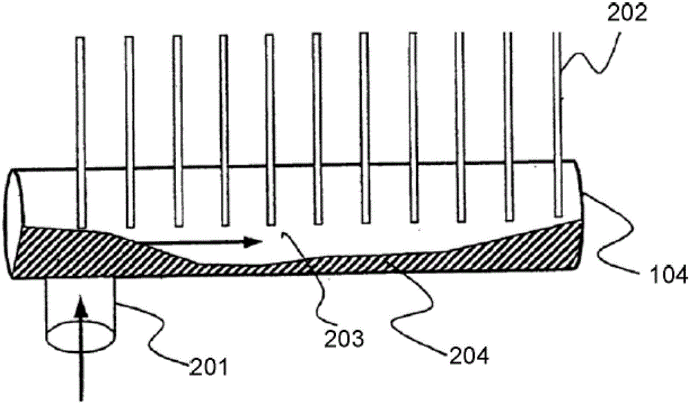
[0027] The refrigerant pipeline 104 and the oil cooling pipeline 105 are arranged inside the tubular body, and the inlet and outlet of the refrigerant pipeline 104 and the oil cooling pipeline 105 are opened in the tubular body at the second end 103 . The internal pipelines 108 and 109 of the above-mentioned refri...


PUM


Abstract

The invention provides a refrigerant pipeline applied to a heat exchanger. The refrigerant pipeline is arranged inside a tubular machine body of the heat exchanger, and comprises an inlet, an outlet, an outer interface and a plurality of heat-conducting fins, wherein the inlet and the outlet are formed on the same tip of the tubular machine body, and are positioned on the same end part of a pipe body of the refrigerant pipeline; a liquid-state refrigerant is allowed to be introduced from the inlet; the outer interface is formed in a side wall below the pipe body of the refrigerant pipeline, and is used for allowing a gas-state refrigerant to be introduced; and the heat-conducting fins are uniformly fixed on a side wall above the pipe body of the refrigerant pipeline. Moreover, the invention further provides a heat exchanger.

Description

technical field [0001] The invention relates to a refrigerant pipeline and a heat exchanger using the same. Background technique [0002] The heat pump system can continuously absorb heat from a low-temperature heat source, and heat a certain volume of water to the temperature QT required by the user. The coefficient of performance COP=QT / PA (PA refers to power consumption). Because the water is heated at high temperature, the heat pump unit usually operates at a high compression ratio, in which case the performance of the compressor will decrease, and the oil in the compressor will easily deteriorate. Under normal circumstances, lubricating oil can work in the temperature range required by the air conditioner, but when the temperature reaches 110-120 ° C, the lubricating oil usually loses its intrinsic viscosity. For this reason, compressor manufacturers usually limit the evaporating and condensing temperatures of the compressor and use jet cooling to cool the lubricating ...

Claims


Application Information

Patent Timeline
Patent Type & Authority Patents(China)
IPC IPC(8): F25B41/00F25B30/06F25B49/00
Inventor 陈睿
Owner CLIMAVENETA CHATUNION REFRIGERATION EQUIP SHANGHAI
Why Eureka
Try Eureka