
Method for improving precision of laser range finder

A laser range finder, precision technology, applied in the direction of measuring distance, instruments, measuring devices, etc., can solve the problems of increased motor drive power consumption, high identity requirements, and instrument identification errors

Inactive Publication Date: 2013-04-03
王振兴
View PDF7 Cites 17 Cited by
  • Summary
  • Abstract
  • Description
  • Claims
  • Application Information

AI Technical Summary

Problems solved by technology

Specifically, the structure uses a motor to drive a reflector to reflect the calibration light projected by the laser source E into the receiving cavity of the optical path of the rangefinder with an open end. After diffuse reflection is formed in the receiving cavity, the photosensitive element in the receiving cavity D receives the light signal and compares the signals. The defect of this structure is: the reflector is an important part involved in the reference positioning during the light receiving process, so the identity of returning to the initial position after rotation is relatively high. , and in the actual use process, the reflector often has mechanical deformation structure errors caused by rotation or movement. This error is introduced into the calibration optical system, which will greatly affect the calibration accuracy; The switching position must be locked accurately, and the usual reflectors are of different structures and need to be locked with other components. In order to reach the correct switching position, the power consumption of the motor drive will often increase; in addition, the diffuse reflection of the reflector The light receiving method has poor stability and is easy to be mixed with external light, resulting in wrong identification of the instrument, reducing the stability of the instrument, and affecting the accuracy of the measurement results
So the effect of LD is also difficult to subtract

Method used


Image

  • Method for improving precision of laser range finder
  • Method for improving precision of laser range finder
  • Method for improving precision of laser range finder

Examples


Embodiment Construction

[0033] In order to make the object, technical solution and advantages of the present invention clearer, the present invention will be further described in detail below in conjunction with the accompanying drawings and embodiments. It should be understood that the specific embodiments described here are only used to explain the present invention, not to limit the present invention.

[0034] The present invention improves the method for the precision of laser range finder, comprises the transmitting and receiving system that semiconductor laser transmitter LD and APD are formed, and it comprises the following steps:

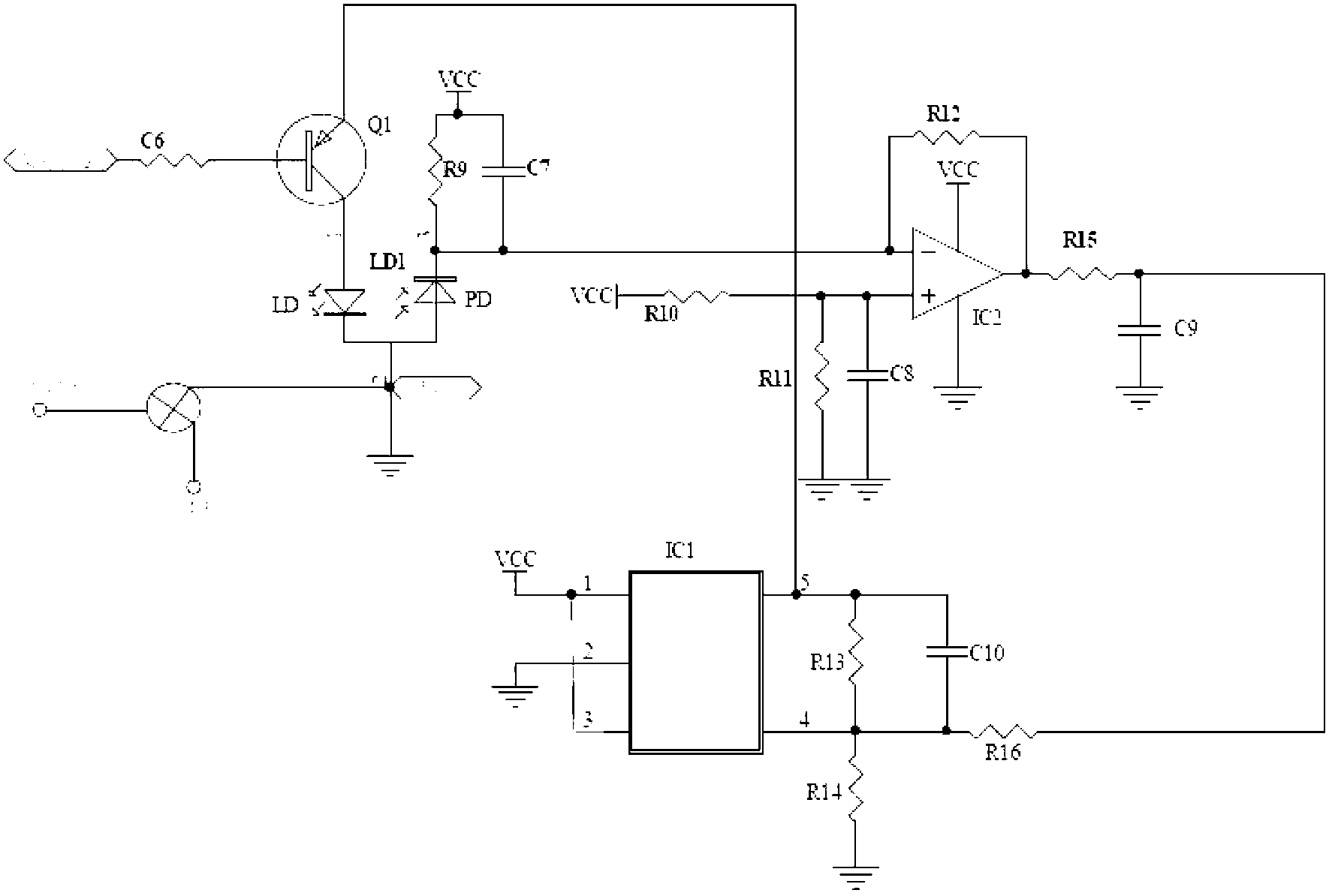
[0035] S10: Compensate and eliminate the impact of the environment on LD

[0036] Specifically, in step S10, the current signal of the ground terminal or power supply terminal of the LD circuit is drawn out, amplified, mixed, and phase-detected to obtain the phase; at the same time, the measurement signal emitted by the LD is also amplified and mixed by the APD. 1...


PUM


Abstract

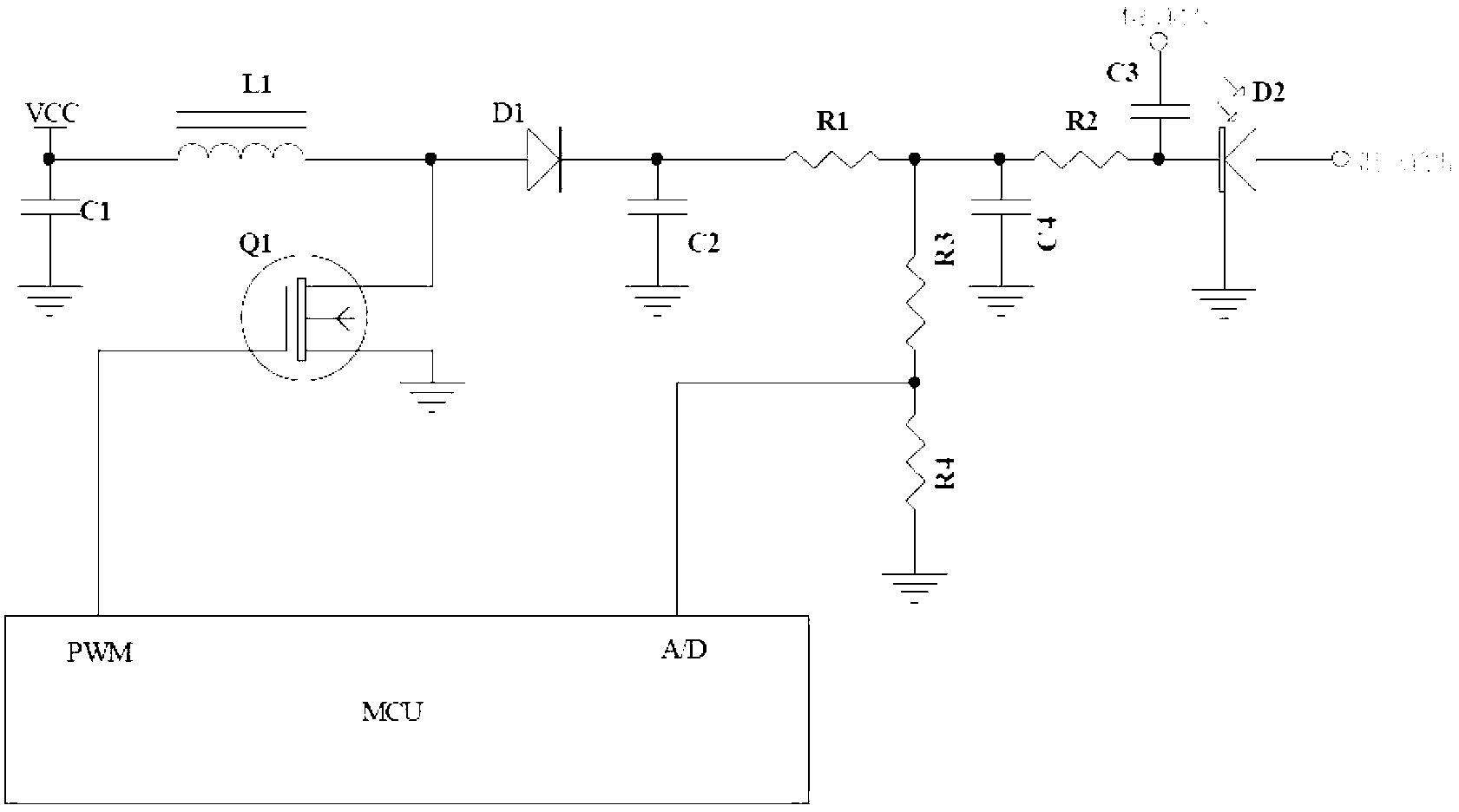
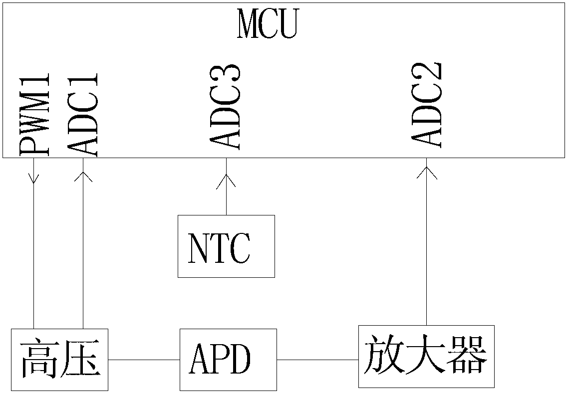
The invention discloses a method for improving precision of a laser range finder. The method comprises the following steps: S10: compensating and cancelling the influence, caused by an LD (Laser Diode), on the environment; S11, compensating and cancelling the influence, caused by environment, on an APD (Avalanche Photon Diode), wherein step S11 comprises the following steps: firstly, obtaining a temperature shift coefficient of the APD, using an NTC (Negative Temperature Coefficient) to sample the environment temperature of a photosensitive element to obtain a temperature value; then, calculating the increased volt quantity of a bias voltage of the APD when the temperature raises one DEG C according to the temperature compensation coefficient of the APD; and finally, controlling a booster circuit, so that an ADC (Analog to Digital Converter) samples the voltage to a PWM (Pulse-Width Modulation)-control booster circuit to obtain the corresponding bias voltage, and compensating the bias voltage of the APD by adopting an APD temperature compensation rate. The temperature shift coefficient of the APD is measured, the amplifying logarithm to the APD is compensated, and the amplifying factor of the APD is consistent at any temperature, so that the consistence of the product is ensured during large-scale production.

Description

technical field [0001] The invention belongs to the technical field of laser measuring instruments, and relates to a method for improving the precision of a laser range finder. Background technique [0002] At present, in order to improve the accuracy of the laser rangefinder, the following solutions are generally adopted: [0003] Solution 1: Set two APDs and one LD in the laser range finder. Because the influence of the environment on each device is the same. So use one LD to transmit laser to two APDs to receive at the same time. The inner light path is emitted by internal emission, and the outer light path is used to test the distance outside. The influence of the environment can be subtracted by subtracting the distance of the inner light path from the distance measured by the outer light path. The disadvantage of this scheme is the high cost of APD. [0004] Scheme 2, setting an LD, an APD, and an optical baffle in the laser rangefinder. The LD first emits to the...

Claims


Application Information

Patent Timeline
Patent Type & Authority Applications(China)
IPC IPC(8): G01C3/00
Inventor 王振兴
Owner 王振兴
Learn More