Thermal wind speed sensing device capable of performing zero compensation automatically and method for measuring wind speeds

A sensing device and zero-point compensation technology, which is applied in the direction of measuring fluid velocity by using thermal variables, can solve problems such as zero-point drift, anemometer sensitivity and accuracy problems, and hinder the improvement of thermal anemometer accuracy and sensitivity, so as to achieve accurate measurement , the effect of a wide range of wind speed measurement

Inactive Publication Date: 2013-04-03
SOUTHEAST UNIV
View PDF6 Cites 7 Cited by
  • Summary
  • Abstract
  • Description
  • Claims
  • Application Information

AI Technical Summary

Problems solved by technology

As we all know, the zero temperature drift of typical thermal anemometers has always been a major obstacle to the improvement of the accuracy and sensitivity of thermal anemometers
Since the temperature of the environment and the temperature of the sensor are constantly changing, the zero point always drifts to varying degrees, which is a big problem for the sensitivity and accuracy of the anemometer.

Method used


Image

  • Thermal wind speed sensing device capable of performing zero compensation automatically and method for measuring wind speeds
  • Thermal wind speed sensing device capable of performing zero compensation automatically and method for measuring wind speeds
  • Thermal wind speed sensing device capable of performing zero compensation automatically and method for measuring wind speeds

Examples


Embodiment Construction

[0016] The technical solution of the present invention will be described in detail below in conjunction with the accompanying drawings.

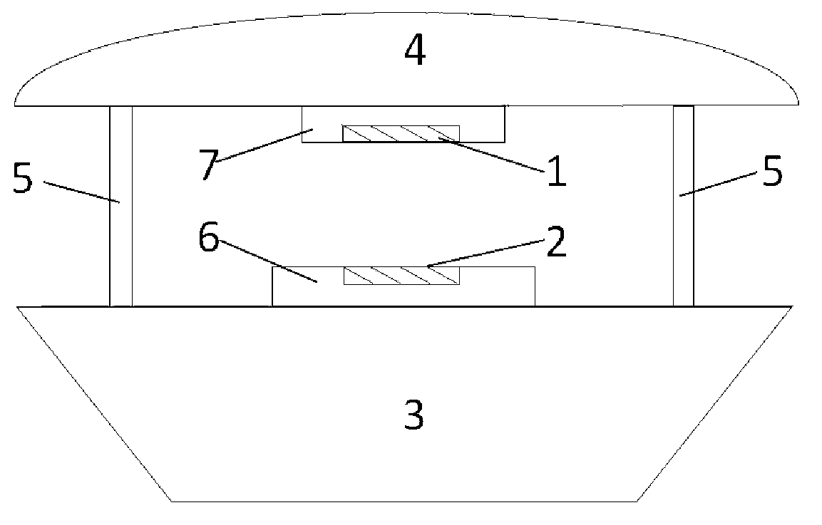
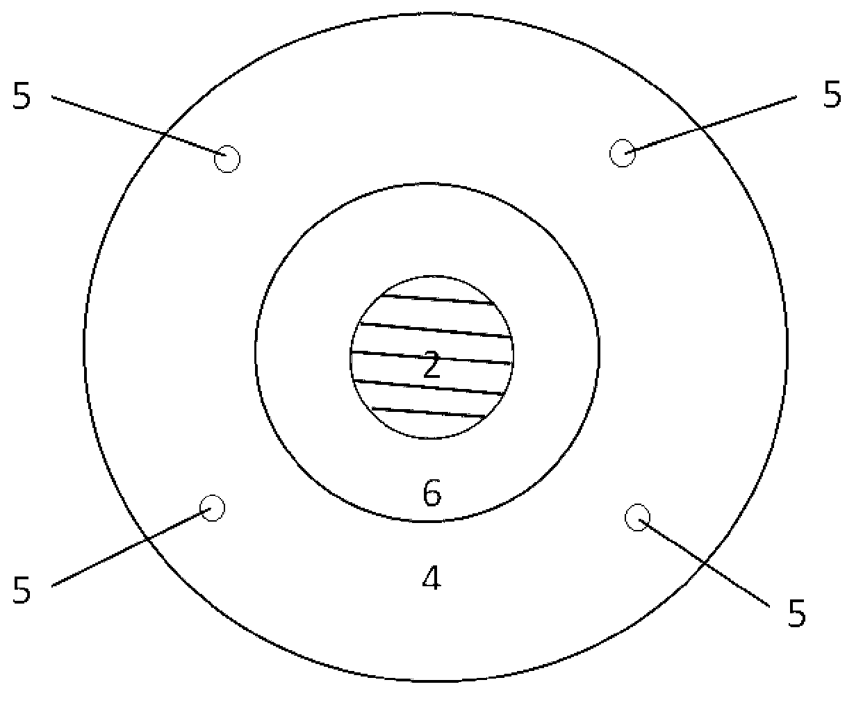
[0017] Such as figure 1 and figure 2 As shown, a thermal wind speed sensor device with automatic zero point compensation of the present invention includes

[0018] An upper sensor chip 1, a lower sensor chip 2, a top case 3, a bottom case 4, a support column 5, a lower support platform 6 and an upper support platform 7. The support columns 5 are connected between the top case 3 and the bottom case 4 , and gaps are formed between adjacent support columns 5 . The outside wind enters the thermal wind speed sensing device from the gap between the support columns 5 . The upper platform 7 is connected to the bottom of the top case 3 , and the upper sensor chip 1 is embedded in the bottom of the upper platform 7 . The lower support platform 6 is connected to the top surface of the bottom case 4 , and the lower sensor chip 2 is embedded on the ...


PUM


Abstract

The invention discloses a thermal wind speed sensing device capable of performing zero compensation automatically. The device comprises an upper sensor chip, a lower sensor chip, a top casing, a bottom casing, support column bodies, a lower support platform and an upper support platform. The upper sensor chip is embedded at the bottom of the upper support platform, and the lower sensor chip is embedded at the top of the lower support platform; and the upper sensor chip is a wind speed sensor chip in a constant-temperature-difference mode, and the lower sensor chip is a wind speed sensor chip in a constant-power mode. A method for measuring wind speeds through the thermal wind speed sensing device comprises placing a thermal wind speed sensing device at a place of a wind speed to be tested; performing measurement, wherein the upper sensor chip works in a constant temperature difference working mode, the lower sensor chip works in a constant temperature working mode, and a single-chip microcomputer system measures and calculates wind speeds; and performing next measurement. The thermal wind speed sensing device can perform zero compensation automatically when used for measuring the wind speeds and has the advantages of being accurate in measurement and wide in wind speed measurement range.

Description

technical field [0001] The invention relates to a thermal wind speed sensing device, in particular to a thermal wind speed sensing device capable of automatic zero point compensation, and also to a method for measuring wind speed using the thermal wind speed sensing device. Background technique [0002] Wind speed and wind direction are very important parameters to reflect meteorological conditions, and have an important impact on environmental monitoring, air conditioning, and industrial and agricultural production. Therefore, it is of great practical significance to quickly and accurately measure wind speed and wind direction. As we all know, the zero-point temperature drift of typical thermal anemometers has always been a major obstacle to the improvement of the accuracy and sensitivity of thermal anemometers. Since the temperature of the environment and the temperature of the sensor are constantly changing, the zero point always drifts to varying degrees, which is a big ...

Claims


Application Information

Patent Timeline
Patent Type & Authority Applications(China)
IPC IPC(8): G01P5/10
Inventor 秦明陈升奇周麟
Owner SOUTHEAST UNIV
Why Eureka
Try Eureka