Vacuum refrigerating tumbling machine

A technology of vacuum refrigeration and tumbling machine, which is applied in the fields of slaughtering, meat processing equipment, food science, etc. It can solve the inconvenient operation position of the mobile vacuum tumbling machine, which affects the production and economic benefits of meat products, and is not conducive to the quality and freshness of meat products. and other problems, to achieve the effect of shortening the refrigeration time, fast refrigeration speed and guaranteed quality

Active Publication Date: 2013-04-10
河北诚业智能科技股份有限公司
View PDF11 Cites 10 Cited by
  • Summary
  • Abstract
  • Description
  • Claims
  • Application Information

AI Technical Summary

Problems solved by technology

The traditional vacuum tumbler needs to work in a constant temperature room to ensure the quality of meat products, but building a constant temperature workshop requires a lot of money, and it is extremely inconvenient to move the vacuum tumbler, which affects the production and quality of meat products. Improvement of economic benefits
However, the existing vacuum refrigeration tumblers in the market use the method of cylinder wall refrigeration, which takes a long time to reduce the meat products to the required temperature, and it is during this time that the quality of meat products is most likely to change, and the cylinder wall refrigeration The cooling method is uneven, the local temperature difference is large, the temperature of the meat products close to the cylinder wall is low, and the temperature of the meat products far away from the cylinder wall is relatively high, which is not conducive to the quality and freshness of the meat products.

Method used


Image

  • Vacuum refrigerating tumbling machine
  • Vacuum refrigerating tumbling machine
  • Vacuum refrigerating tumbling machine

Examples


Embodiment Construction

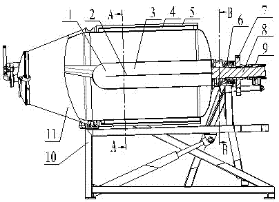
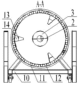
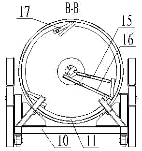
[0017] A vacuum refrigeration tumbler, comprising a tumbler barrel 11 connected to a frame 10, a main shaft 8 fixedly connected to the tumbler barrel 11, and a drive mechanism connected to the main shaft 8, the main shaft 8 being provided with a main water inlet 18 and The main water outlet 19, the outer side of the main shaft 8 is provided with a main shaft sealing sleeve 9 with a water inlet and a water outlet, the inner and outer walls of the tumbler 11 are successively provided with a cooling layer 4 and an insulating layer 5, and the cooling layer 4 is provided with a water inlet And the water outlet, the key is: add an intermediate refrigeration compartment 3 along the axis inside the above-mentioned tumbler 11, and a partition 2 is arranged inside the intermediate refrigeration compartment 3, and the intermediate refrigeration compartment 3 is separated into a water inlet chamber and an outlet chamber by means of the partition board 2 The water inlet bin communicates wit...


PUM


Abstract

The invention relates to a vacuum refrigerating tumbling machine, which aims to solve the technical problem that the current vacuum refrigerating tumbling machine is long in refrigerating time and larger in local difference in temperature. The technical scheme adopted is that the vacuum refrigerating tumbling machine comprises a tumbling barrel connected with a frame, a main shaft fixedly connected with the tumbling barrel, and a driving mechanism connected with the main shaft, wherein a refrigerating layer and an insulating layer are sequentially arranged between the inner and outer walls of the tumbling barrel respectively; the key point is that a middle refrigerating cabin is further arranged inside the tumbling barrel along the axis, the middle refrigerating cabin is internally provided with a partition board and is divided into a water inlet cabin and a water outlet cabin through the partition board; the water inlet cabin is communicated with a main water inlet via a first water inlet pipeline while the water outlet cabin is communicated with the water inlet of the refrigerating layer via a first water outlet pipeline, and the water outlet of the refrigerating layer is communicated with a main water outlet through a second water outlet pipeline to form a serial cold water circulating system. The invention has the technical effects that the vacuum refrigerating tumbling machine is uniform in cooling, small in local difference in temperature, fast refrigerating speed and good effect, and 1 / 3 refrigerating time can be shortened, and the quality of meat products can be better ensured.

Description

technical field [0001] The invention belongs to the technical field of food processing, and relates to a tumbler, in particular to a vacuum refrigeration tumbler. Background technique [0002] Vacuum tumbler is the key equipment in meat processing. It uses the principle of physical impact in a vacuum state to make meat or meat stuffing turn up and down in the tumbler, hitting and beating each other, so as to achieve massage and pickling. . The pickling solution is fully absorbed by the meat, which enhances the binding force and elasticity of the meat, improves the taste and section effect of the product, enhances the water retention and increases the yield, and improves the internal structure of the product. The traditional vacuum tumbler needs to work in a constant temperature room to ensure the quality of meat products, but building a constant temperature workshop requires a lot of money, and it is extremely inconvenient to move the vacuum tumbler, which affects the prod...

Claims


Application Information

Patent Timeline
Patent Type & Authority Applications(China)
IPC IPC(8): A22C17/00
Inventor 李会岗
Owner 河北诚业智能科技股份有限公司
Why Eureka
Try Eureka