Supercharge Your Innovation With Domain-Expert AI Agents!

Catalytic conversion catalyst regenerator

A catalytic conversion and catalyst technology, applied in the direction of catalyst regeneration/reactivation, physical/chemical process catalysts, chemical instruments and methods, etc., can solve the problems of pressure fluctuation, too low dense phase bed, uneven distribution of main air, etc. To achieve the effect of uniform temperature distribution, not easy to dilute phase over-temperature

Active Publication Date: 2013-04-10
CHINA PETROLEUM & CHEM CORP +1
View PDF13 Cites 10 Cited by
  • Summary
  • Abstract
  • Description
  • Claims
  • Application Information

AI Technical Summary

Problems solved by technology

However, when the circulation rate of the catalyst needs to be greatly increased, the existing catalyst mixing and cooling technology cannot stably provide the catalyst with uniform heat and fluidization for the riser reactor
For the complete combustion method, when the carbon monoxide is not completely burned in the dense phase and rises to the dilute phase combustion, the afterburn phenomenon will occur. The main reasons for the occurrence include uneven distribution of the main air, poor fluidization of the catalyst, too low dense bed, fresh Catalyst replenishment is too fast, combustion accelerant is insufficient, the external heater returns to the catalyst bypass, etc. After the tail combustion occurs, the dilute phase temperature often rises rapidly, approaching or exceeding 800°C, thus causing the regenerator to overheat
Overheating of the regenerator will damage the equipment, internal components and lining in the settler, causing pressure fluctuations. If not handled properly, it will affect the smooth operation of the device
If a platinum-based carbon monoxide combustion aid is used, the NOx emission of the catalytic cracking unit will increase due to the catalytic effect of platinum

Method used


Image

  • Catalytic conversion catalyst regenerator
  • Catalytic conversion catalyst regenerator
  • Catalytic conversion catalyst regenerator

Examples


Embodiment approach 1

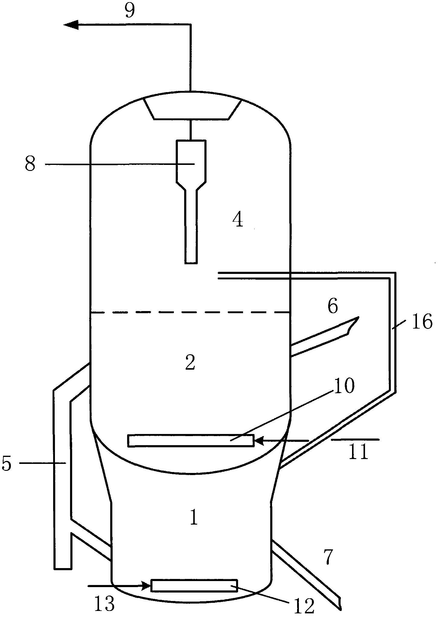
[0036] figure 1 It is a schematic diagram of the basic equipment of Embodiment 1 provided by the present invention.

[0037] Such as figure 1 As shown, the buffer zone 1, the regeneration zone 2 and the settlement zone 4 are arranged vertically from bottom to top. The cooling zone 5 is juxtaposed between the regeneration zone 2 and the buffer zone 1. The regeneration zone 3 is a single-stage regeneration method, and the regeneration zone 2 and the settlement zone Zone 4 adopts direct connection to the vessel wall. The standby catalyst from the reactor enters the regeneration zone 2 through the standby inclined pipe 6 and is evenly distributed on the upper part of the dense phase bed through the distributor. The main air enters from the bottom of the regeneration zone 2 through the pipeline 11 from the main air distribution plate 10 and flows upward. It comes into contact with the spent catalyst flowing downward by gravity in countercurrent and the coke combustion reaction occurs,...

Embodiment approach 2

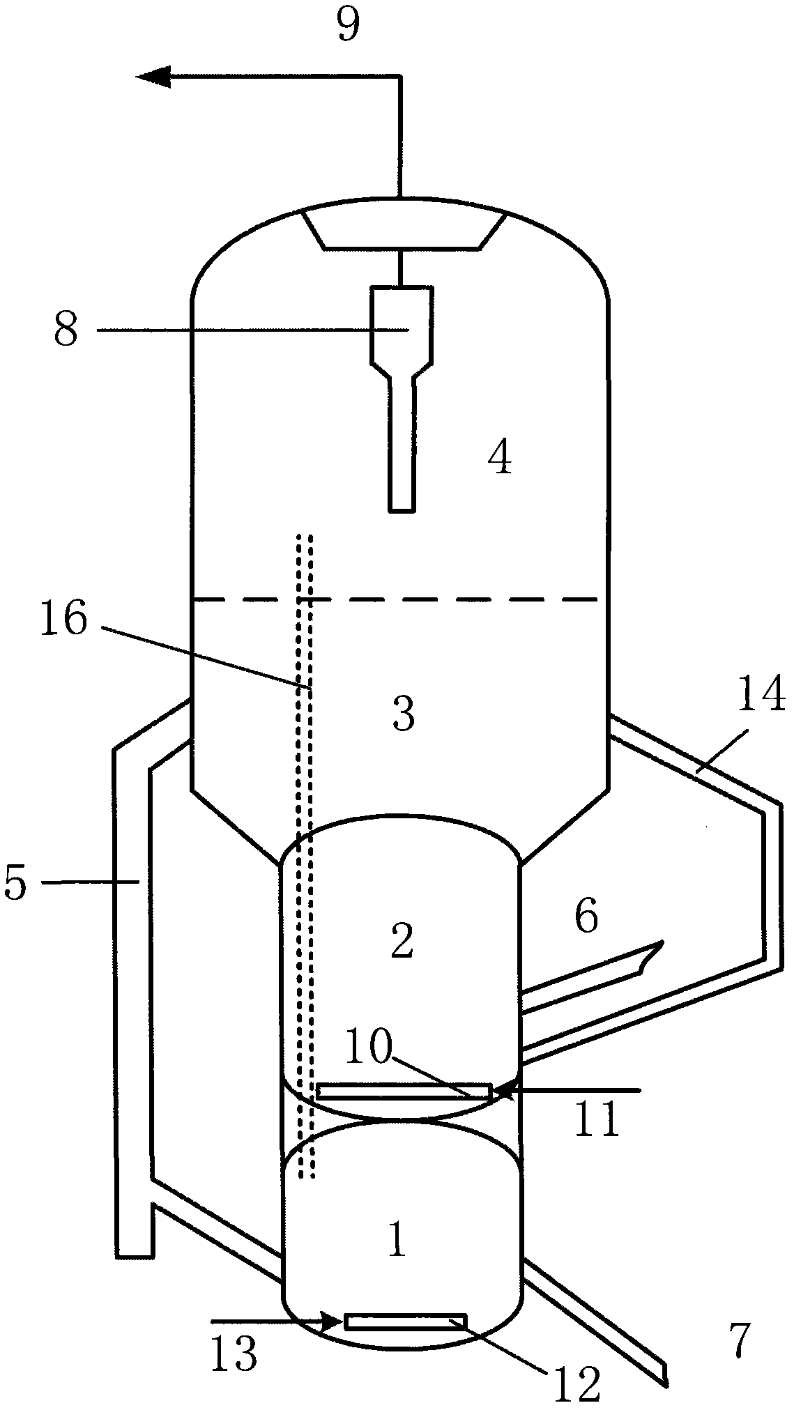
[0039] figure 2 It is a schematic diagram of the basic equipment of the second embodiment provided by the present invention.

[0040] Such as figure 2 As shown, the buffer zone 1, the regeneration zone 2, the regeneration zone 3, and the settlement zone 4 are arranged vertically from bottom to top. The cooling zone 5 is juxtaposed between the regeneration zone 2, the regeneration zone 3 and the buffer zone 1. The regeneration zones 2 and 3 are With the coke tank regeneration method, the regeneration zone 3 and the settlement zone 4 adopt the method of direct connection to the wall. The spent catalyst from the reactor enters the bottom of the coke-tank regeneration zone 2 through the spent inclined pipe 6 and is mixed with the high temperature catalyst returned by the circulating pipe 14 to increase the temperature of the spent catalyst. The main air flows from the main air distribution plate 10 through the pipeline 11 The bottom of the coking tank regeneration zone 2 enters. Af...

Embodiment approach 3

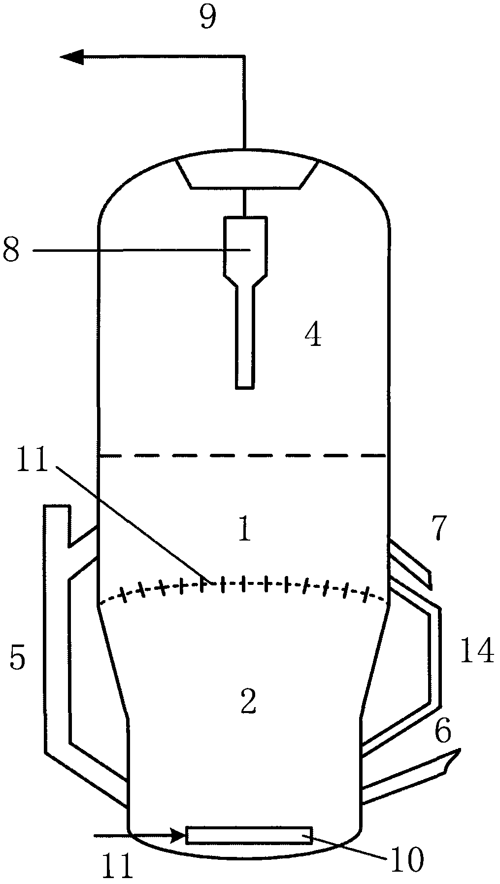
[0042] image 3 It is a schematic diagram of the basic equipment of the third embodiment of the present invention.

[0043] Such as image 3 As shown, the regeneration zone 2, the buffer zone 1 and the settlement zone 4 are arranged vertically from bottom to top. The cooling zone 4 is juxtaposed between the regeneration zone 2 and the buffer zone 1. The regeneration zone 2 is a single-stage regeneration method, and the buffer zone 1 and the settlement zone Zone 4 adopts direct connection to the vessel wall. The standby catalyst from the reactor enters the regeneration zone 2 through the standby inclined pipe 6 and is evenly distributed on the upper part of the dense phase bed through the distributor. The main air enters from the bottom of the regeneration zone 2 through the pipeline 11 from the main air distribution plate 10 and flows upward. The coke combustion reaction occurs when the catalyst is in countercurrent contact with the spent catalyst flowing downward by gravity. The...


PUM


Abstract

A catalytic conversion catalyst regenerator comprises a regeneration zone, a settling zone, a buffer zone and an optional cooling zone, wherein the buffer zone is adjacent to the regeneration zone, the buffer zone is provided with a catalyst inlet and a catalyst outlet, and the catalyst inlet is connected with the cooling zone or / and an inclined tube to be regenerated, and is preferably connected with the cooling zone; and the catalyst outlet is connected with a regeneration inclined tube. A catalytic conversion catalyst regeneration method comprises the following steps: a catalyst to be regenerated enters the regeneration zone of the regenerator, contacts with an oxygen-containing gas, and undergoes a combustion reaction, the obtained regenerated catalyst enters the buffer zone, is cooled, and is returned to a reactor, and a flue gas is discharged from the top of the settling zone. The buffer zone adopted in the invention enables the catalyst temperature distribution to be uniform, has a cooling effect on the dilute phase of the regenerator, and allows the overheat phenomenon of the dilute phase to difficultly appear.

Description

Technical field [0001] The invention relates to a regenerator for coking a carbon-containing catalyst in a catalytic cracking process. Background technique [0002] While the feedstock is undergoing catalytic cracking reaction, due to the condensation reaction, in addition to the production of light hydrocarbons, a part of coke is also produced, which is deposited on the catalyst, thereby reducing the activity and selectivity of the catalyst. Therefore, the high temperature oxidation regeneration method is used to burn off the coke on the catalyst to restore the performance of the catalyst. This process is called catalyst regeneration. The catalyst with deposited coke is usually called the spent catalyst, and the catalyst after oxidation regeneration is called It is a regenerated catalyst. The scorching process is completed in the regenerator. According to the type of fluidized bed of the regenerator, it can be divided into turbulent bed, fast bed and conveying bed; according to...

Claims


Application Information

Patent Timeline
IPC IPC(8): B01J38/30B01J38/34
Inventor 崔守业马建国常学良龚剑洪刘守军
Owner CHINA PETROLEUM & CHEM CORP
Features
  • R&D
  • Intellectual Property
  • Life Sciences
  • Materials
  • Tech Scout
  • Unparalleled Data Quality
  • Higher Quality Content
  • 60% Fewer Hallucinations
Learn More