Centrifugal classifier

A technology of centrifugal classification and separation hood, applied in centrifuges, separation of sediments by centrifugal force, separation methods, etc., can solve the problems of unstable flow, uncertain classification particle size, low classification efficiency, etc., to improve classification efficiency, reduce The effect of mixed thickness and high classification efficiency

Inactive Publication Date: 2013-04-10
刘晔
View PDF7 Cites 8 Cited by
  • Summary
  • Abstract
  • Description
  • Claims
  • Application Information

AI Technical Summary

Problems solved by technology

[0004] The purpose of the present invention is to overcome the problems of low classification efficiency, uncertain classification

Method used


Image

  • Centrifugal classifier

Examples


Embodiment 1

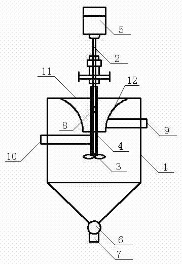
[0022] Such as figure 1 As shown in the structural diagram of this centrifugal classifier, it at least includes a body 1, a feed nozzle 10, a discharge pipe 9, and a sand discharge port 7, a discharger 6, an impeller 3, an air inlet 8, a cover 12, and a motor 5. End cap 11 and rotating shaft 2.

[0023] The main body 1 is a hollow cavity structure formed by connecting two parts of a cylindrical cavity and a conical cavity, wherein the lower end of the cylindrical cavity is fixedly connected with the large end surface of the conical cavity; the upper part of the main body 1 passes through the end The cover 11 is sealed, the upper end of the hollow cavity inside the body 1 is fixed with a separation cover 12, the separation cover 12 is connected with one end of the discharge pipe 9, the other end of the discharge pipe 9 extends outside the body 1, and the side of the body 1 is also fixed with Feed pipe 10; motor 5 is fixed on the upper part of body 1, and motor 5 is connected w...

Embodiment 2

[0027] The body 1 in the above embodiment is a vertical structure, and the feeding pipe 10 is fixed along the involute-tangential direction of the upper end of the side of the body 1, and the horizontal height of the upper and lower edges of the feeding port 10 is not higher than the separation cover 12. The horizontal height of the upper and lower edges is in the middle of the separation cover 12 .

[0028] The form that the feed pipe 10 is arranged along the involute-tangential direction needs to pump the mixed material into the body 1 with a sand pump. When the capacity of the material is insufficient, it is thrown up by the impeller 3 to replenish energy and be classified again.

Embodiment 3

[0030] The feed pipe 10 in Embodiment 1 can also extend into the body 1 through the side wall of the body 1 , and finally communicate with the sleeve 4 outside the rotating shaft 2 . Driven by the motor 5 to rotate the impeller 3, the slurry can enter the sleeve 4 under the feed pressure of less than 0.06Mpa, and rotate at a high speed in the cylindrical column of the body 1 under the rotation of the impeller 3 to realize the slurry (or gas) ) classification, while the fine-grained grade, water, and gas can enter the body 1 through the air inlet 8 after entering the sleeve 4 .

[0031] Since the centrifugal classifier operates under a relatively small pressure (0.01 mpa< p<0.16mpa), or self-priming without pressure, the swirl speed is low, thereby reducing the loss and energy consumption loss. While improving the classification efficiency, it also achieves the purpose of energy saving. There is no internal circulation, no pulp "short circuit", and the operation is stable. Su...


PUM

PropertyMeasurementUnit
Cone angleaaaaaaaaaa

Abstract

The invention relates to classifying equipment, in particular to a centrifugal classifier, which comprises a body, a feed pipe opening, a discharge pipe, a sand discharge port, a discharger, an impeller, an air inlet, a cover, a motor, an end cover and a rotation shaft. The centrifugal classifier is characterized in that the upper part of the body is sealed by the end cover, a separating cover is fixedly arranged on the upper end of a hollow cavity body in the body and connected with one end of the discharge pipe, the other end of the discharge pipe extends outside the body, and a feed pipe is fixedly arranged on the side of the body; the motor is fixedly arranged on the upper part of the body and is in driving connection with the impeller through the rotation shaft which extends into the body and is coaxial with the body; the impeller is arranged on the lower end of the separating cover, a sleeve is sheathed outside the rotation shaft, and the air inlet is formed in the side wall of the sleeve, which is positioned in the separating cover; and the discharger is connected to the bottom of the body, and the lower end of the discharger is connected with the sand discharge port. The centrifugal classifier has the advantages of high classifying efficiency, certain classifying particle size, stable classifying effect, energy saving and wear resistance, and the classifying particle size can be regulated.

Description

technical field [0001] The invention relates to a classifying device, in particular to a centrifugal classifier used for classifying two-phase or three-phase mixtures in liquid, solid and gas according to particle size and specific gravity. Background technique [0002] In mining, petroleum, environmental protection, chemical and other industries, mixed slurry (or solid-containing gas) needs to be separated by classification equipment, usually using cyclone or cyclone dust collector for coarse and fine classification or gas and solid separate. In mines, hydrocyclones are usually used in conjunction with ball mills to form a grinding-classification closed-circuit circulation system. [0003] The disadvantages of the existing cyclone classification are: (1) The classification efficiency is low, usually only 30% to 40%, the flow state of the classification is complicated and disordered, and the coarse and fine are mixed with each other. Therefore, in the next process—grinding ...

Claims


Application Information

Patent Timeline
IPC IPC(8): B04B5/00B01D21/26B01D45/14
Inventor 刘晔刘敏婕
Owner 刘晔
Why Eureka
Try Eureka