Novel valve core with spring seat

A spring seat, a new type of technology, applied in the hydraulic field, can solve the problems of low assembly success rate, short guiding effect of the valve stem, spring seat and valve stem falling off, etc., and achieve the goal of improving the assembly success rate, reducing assembly requirements, and increasing the guide length Effect

Inactive Publication Date: 2013-04-10
SAIKESI HYDRAULIC TECH CO LTD
View PDF8 Cites 2 Cited by
  • Summary
  • Abstract
  • Description
  • Claims
  • Application Information

AI Technical Summary

Problems solved by technology

In the prior art, the assembly success rate of the lower valve, especially where the lower valve stem is located, is relatively low. The reason for this is that the spring seat has a short guiding effect on the valve stem and the installation space is limited during the assembly process. If it falls off, there is not enough space for the screw plug to be tightened at the valve cavity port. If the screw is not tightened tightly, the sealing ring will lose its sealing effect. Therefore, how to solve the problem of frequent falling off of the spring seat and improve the assembly success rate of the valve is to improve the production efficiency of the valve and Premise of quality

Method used


Image

  • Novel valve core with spring seat
  • Novel valve core with spring seat
  • Novel valve core with spring seat

Examples


Embodiment Construction

[0017] Embodiments of the present invention will be described in further detail below in conjunction with the accompanying drawings.

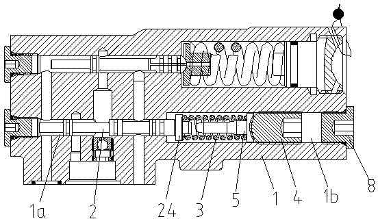
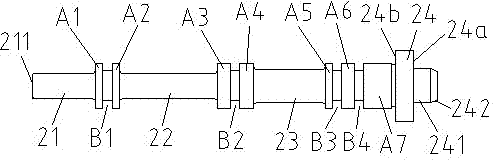
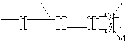
[0018] Figures 1 to 2 It is a structural schematic diagram of the present invention.

[0019] The reference signs are: the first annular sealing boss A1, the second annular sealing boss A2, the third annular sealing boss A3, the fourth annular sealing boss A4, the fifth annular sealing boss A5, the sixth annular sealing boss Sealing boss A6, seventh annular sealing boss A7, first annular groove B1, second annular groove B2, third annular groove B3, fourth annular groove B4, valve body 1, lower valve cavity 1a, Assembly cavity 1b, spool rod body 2, front rod section 21, front end surface 211, middle rod section 22, rear rod section 23, spring seat 24, positioning annular surface 24a, limiting annular surface 24b, spring guide rod 241, taper guide Inclined surface 242, compression spring 3, pressure regulating screw plug 4, spring back seat 5,...


PUM


Abstract

The invention discloses a novel valve core with a spring seat. The novel valve core comprises a valve core rod body which is slidably assembled in a lower valve cavity of a valve body, wherein seven annular sealing bosses are arranged on the valve core rod body; the circumferential surface of each annular sealing boss is slidably matched with the inner peripheral wall of the lower valve cavity through liquid sealing; the tail part of the valve core rod body is integrally provided with the spring seat connected to a back face of the seventh annular sealing boss to form a novel spring seat valve core structure with the spring seat; a spring guide rod is arranged in the center of the spring seat; a compression spring is sleeved on the spring guide rod; the front end of the compression spring is abutted against and matched with a positioning annular face of the spring seat; the valve core rod body is abutted against and assembled in the lower valve cavity of the valve body through the compression spring; and a pressure adjusting spiral plug is spirally pressed at the rear end of the compression spring. The novel valve core has the advantages of simple structure, convenience in machining, low assembly requirement and capabilities of greatly improving the mounting success rate of a PVECVP valve and reducing the production and manufacturing cost, and has the characteristics of high mounting speed and stable performance.

Description

technical field [0001] The invention relates to the field of hydraulic technology, in particular to a valve core structure used in PVECVP series hydraulic valves, in particular to a new type of valve core with a spring seat. Background technique [0002] At present, the PVECVP valve is a combined valve with an upper and lower structure. The upper valve stem and the lower valve stem are respectively installed in the upper valve cavity and the lower valve cavity of the valve body. The tails of the upper valve stem and the lower valve stem are both arc structures. The tail of the arc structure is abutted in the spring seat cavity formed on the spring seat. In the prior art, the assembly success rate of the lower valve, especially where the lower valve stem is located, is relatively low. The reason for this is that the spring seat has a short guiding effect on the valve stem and the installation space is limited during the assembly process. If it falls off, there is not enough ...

Claims


Application Information

Patent Timeline
Patent Type & Authority Applications(China)
IPC IPC(8): F15B13/02
Inventor 吴赛珍高志明
Owner SAIKESI HYDRAULIC TECH CO LTD
Why Eureka
Try Eureka