Tension type magneto-rheological buffer,

A magnetorheological buffer and magnetorheological technology, applied in the field of buffering, can solve the problems of small damping force adjustment range, small damping force, and short effective length of damping channel, so as to achieve the effect of increasing the effective length and meeting the buffering requirements

Inactive Publication Date: 2013-04-10
CHONGQING UNIV
View PDF5 Cites 21 Cited by
  • Summary
  • Abstract
  • Description
  • Claims
  • Application Information

AI Technical Summary

Problems solved by technology

However, in the existing magneto-rheological fluid buffers, the damping channel is arranged at the gap between the working cylinder and the piston, and it is in the form of a straight line. The effective leng

Method used


Image

  • Tension type magneto-rheological buffer,

Examples


Example Embodiment

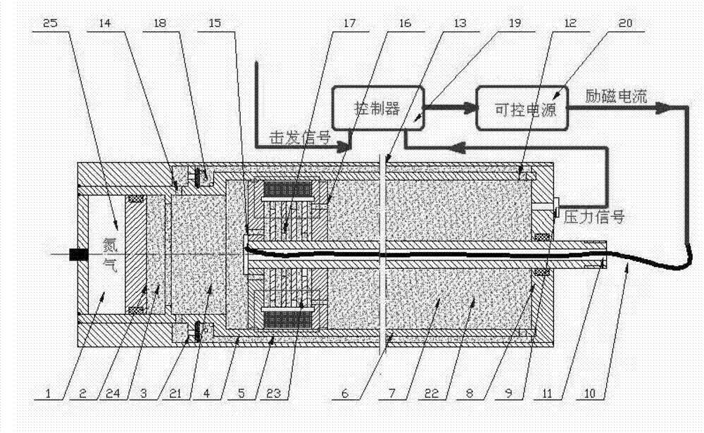
[0021] Please refer to figure 1 , Is a schematic structural diagram of an embodiment of the stretched magnetorheological buffer of the present invention. It includes: a working cylinder I6, a piston I4 and a piston rod 11.

[0022] The piston I4 is arranged in the working cylinder I6, and the working cylinder I6 is divided into a chamber I21 and a chamber II22. One end of the piston rod 11 is fixed on the piston I4, and the other end passes through the chamber II22 and extends out of the working cylinder I6.

[0023] In the above structure, an excitation coil 5 and a multi-stage radial damping passage 23 are provided on the piston I4. Specifically, the piston I4 is provided with an oil cavity. The two ends of the oil cavity are connected to the chamber I21 and the chamber II22 through the oil outlet holes (the left oil outlet hole 15 and the right oil outlet hole 16). The isolation plates 17 are spaced as multi-stage radial damping passages 23 communicating with each other. In a...


PUM


Abstract

The invention provides a tension type magneto-rheological buffer, which comprises a working cylinder I, a piston I and a piston rod, wherein the piston I is arranged in the working cylinder I to separate the working cylinder I into a chamber I and a chamber II, the chamber I and the chamber II are respectively filled with a magneto-rheological material, one end of the piston rod is fixedly arranged on the piston I, the other end of the piston rod penetrates through the chamber II and extends out of the working cylinder I, and the piston I is provided with excitation coils and multiple stages of radial damping passages. When the working cylinder I is subjected to shock, the magneto-rheological material in the chamber II flows into the chamber I through the multiple stages of radial damping passages. Because the piston is provided with the multiple stages of radial damping passages, the effective lengths of the damping passages can be effectively increased when the tension type magneto-rheological buffer is subjected to shock, a larger damping force is outputted, and the buffer requirements during high-speed shock are met.

Description

technical field [0001] The invention relates to the technical field of buffering, in particular to a stretched magneto-rheological buffer that can be used in vehicles, aerospace, heavy machinery, weapons and the like. Background technique [0002] Cushioning refers to the process of alleviating the mechanical vibration of vehicles, aerospace equipment, heavy machinery or weapons when they are subjected to high-speed impact, so that the force is gentle. In practice, there are various impact situations, such as: aircraft landing, gun firing, elevator falling, machine tool parts fast reciprocating movement, etc. These impact situations will cause great impact on mechanical equipment, and the parts of mechanical equipment It will generate a lot of dynamic stress, and may even directly cause damage to parts. Therefore, it is necessary to take buffer measures when the mechanical equipment is impacted. In the prior art, the magnetorheological fluid buffer is a new type of intellig...

Claims


Application Information

Patent Timeline
IPC IPC(8): F16F9/53F16F9/32F16F9/34
Inventor 廖昌荣鞠锐廖峥周治江谢磊
Owner CHONGQING UNIV
Why Eureka
Try Eureka