Laser gyroscope offset frequency method based on external cavity feedback

A laser gyro and frequency bias technology, applied in the field of laser gyro, can solve the problems of increasing cavity loss, coating, and too harsh cavity adjustment, and achieve the effects of eliminating mechanical noise, reducing system complexity, and improving measurement bandwidth

Inactive Publication Date: 2013-04-10
NAT UNIV OF DEFENSE TECH
View PDF4 Cites 5 Cited by
  • Summary
  • Abstract
  • Description
  • Claims
  • Application Information

AI Technical Summary

Problems solved by technology

Faraday rotation optical bias is very sensitive to magnetic field and temperature, so four-frequency differential technology is needed for this purpose. However, since this kind of laser gyroscope needs to place a Faraday chamber in the cavity, it not only increases the cavity loss, but also affects both coating and cavity adjustment. overly demanding

Method used


Image

  • Laser gyroscope offset frequency method based on external cavity feedback
  • Laser gyroscope offset frequency method based on external cavity feedback
  • Laser gyroscope offset frequency method based on external cavity feedback

Examples


Embodiment Construction

[0029] The specific implementation will be described below in conjunction with the accompanying drawings.

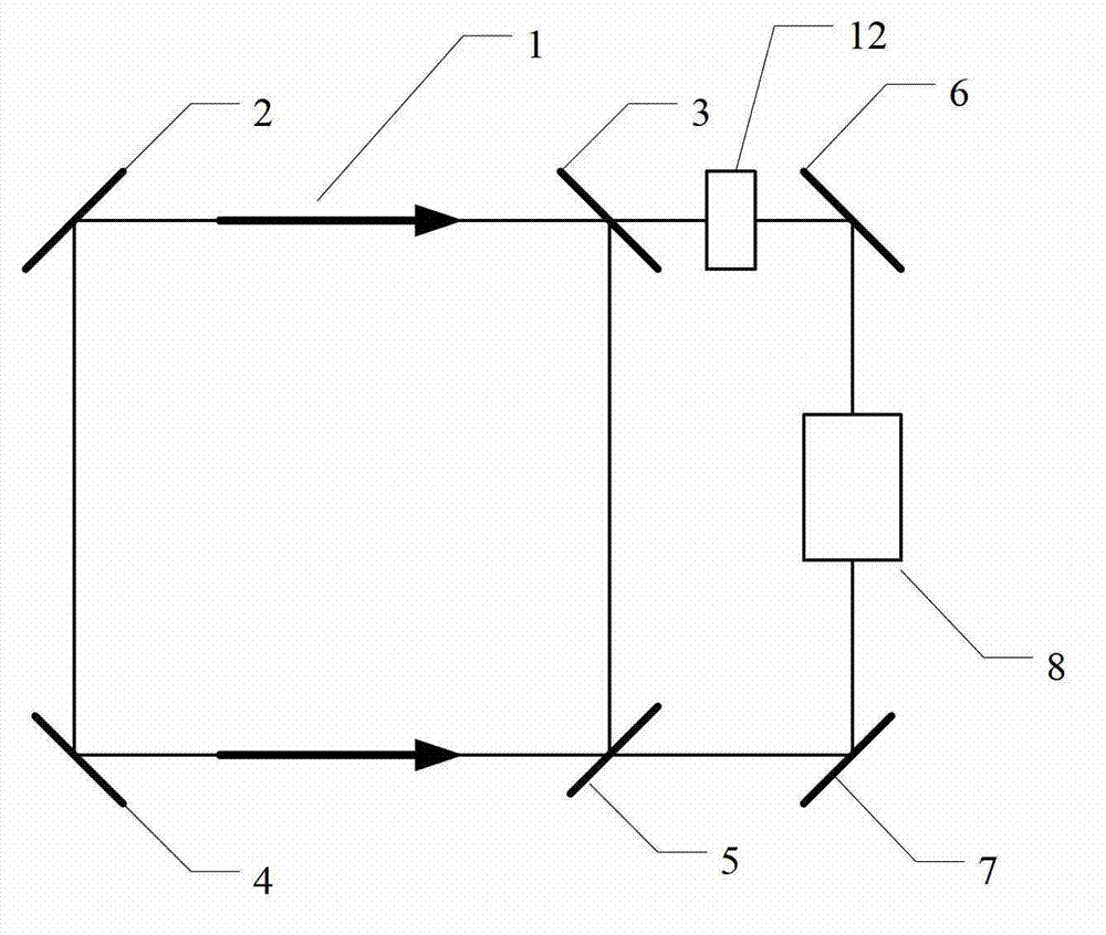
[0030] figure 1 It is a schematic diagram of laser gyro frequency bias based on external cavity feedback, which includes a laser gyro 1 and a fifth mirror 6, a sixth mirror 7, a path length modulation device 12, a non-reciprocal optical device 8, a mirror II 3 and a mirror Feedback external cavity composed of IV5, wherein the laser gyro 1 is composed of reflector I2, reflector II3, reflector III4, and reflector IV5. The laser light transmitted from the reflector II3 is redirected by the fifth reflector 6 and the sixth reflector 7 in the external cavity, and enters the laser gyro resonator from the reflector IV5 again. Similarly, the laser light transmitted from the reflector IV5 passes through the Ⅱ3 re-enters the laser gyro cavity. Due to the feedback of the external cavity, a frequency difference is added between the clockwise and counterclockwise light waves in the ...


PUM


Abstract

The invention relates to a laser gyroscope offset frequency method based on external cavity feedback. The method particularly comprises the following steps of: establishing a feedback external cavity outside a laser gyroscope cavity, and reflecting clockwise beams into a laser resonant cavity; and arranging a nonreciprocal optical device in an external cavity light path, so that feedback light waves of clockwise and anticlockwise light waves have phase difference, and frequency offset is established between the clockwise and anticlockwise light waves of the laser gyroscope. A path length modulation part is arranged in the feedback external cavity light path, and the external cavity light path is modulated, so that the frequency offset of the laser gyroscope is modulated, and an effect similar to mechanical dither is obtained. A modulation signal in a laser gyroscope reading device is filtered by employing a filtering technology, so that an angular velocity signal of laser gyroscope measurement is obtained. According to the method, mechanical noise is not generated, and extremely high modulation frequency can be adopted, so that a response speed of the laser gyroscope is increased.

Description

technical field [0001] The invention relates to a laser gyroscope, in particular to a method for making the laser gyroscope generate bias frequency. Background technique [0002] Laser gyro has the advantages of large dynamic range, no acceleration effect, and simple structure. It is an ideal component for inertial systems, especially strapdown inertial systems, and has been widely used in military and civilian fields. The principle of the laser gyroscope is the Sagnac effect, in which at least one pair of counterpropagating light waves run in its optical resonant cavity. When it rotates around the sensitive axis relative to the inertial space, the frequency of the opposite traveling waves splits to form a beat frequency proportional to the rotation rate, so the rotation information of the laser gyroscope relative to the inertial space can be obtained by measuring the beat frequency. [0003] Due to the energy coupling between opposing traveling waves in the resonant cavity...

Claims


Application Information

Patent Timeline
Patent Type & Authority Applications(China)
IPC IPC(8): G01C19/64
Inventor 汪之国王飞肖光宗
Owner NAT UNIV OF DEFENSE TECH
Why Eureka
Try Eureka