Measuring method and device for steam flow of boiler

A technology of steam flow and measuring device, applied in measuring device, measuring flow/mass flow, liquid/fluid solid measurement, etc., can solve the problems of low precision, long pure lag time, high equipment investment and maintenance cost, and achieve energy-saving control , fuel saving, high precision effect

Inactive Publication Date: 2013-04-10
ANHUI LAND GRP
View PDF6 Cites 2 Cited by
  • Summary
  • Abstract
  • Description
  • Claims
  • Application Information

AI Technical Summary

Problems solved by technology

[0004] There are at least the following technical defects in the control process of steam boilers in the prior art: (1) Various existing instruments cannot measure the evaporation of water inside the bubble bag (that is, the evaporation of water inside the boiler), but can only measure the steam in the bubble bag The steam flow behind the outlet also needs to be compensated for temperature and pressure, and its pure lag time is long and the accuracy is low; (2) the use of special steam flow measurement instruments requires high equipment investment and maintenance costs; (3) due to the inability to quickly Measure the water evaporation accurately, so the optimal control system cannot achieve the goal of optimal combustion

Method used


Image

  • Measuring method and device for steam flow of boiler
  • Measuring method and device for steam flow of boiler

Examples


Embodiment Construction

[0018] The technical scheme of the present invention will be further described below in conjunction with the accompanying drawings and through specific embodiments:

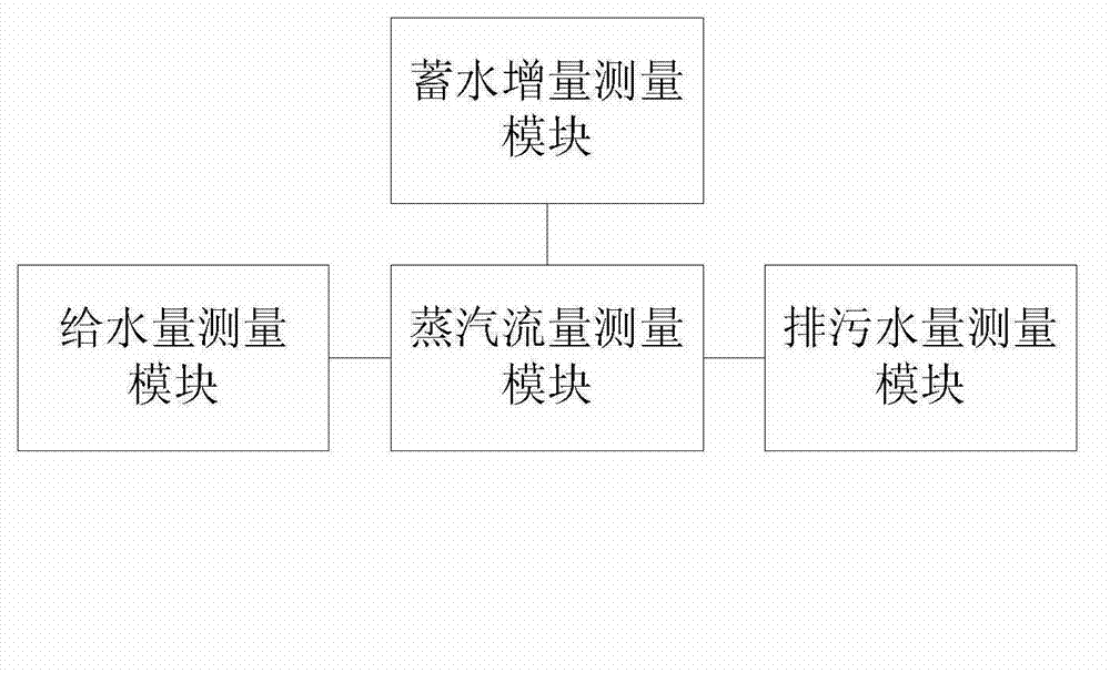
[0019] Such as figure 2 as shown, figure 2 It is a structural schematic diagram of a boiler steam flow measurement device proposed by the present invention.

[0020] refer to figure 2 , a boiler steam flow measurement device proposed by the present invention, comprising:

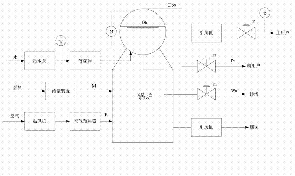
[0021] The water supply measurement module is used to measure the water supply W of the boiler;

[0022] The water storage increment measurement module is used to measure the water storage increment of the boiler drum k1=ρ 水 ×S 汽包水面 , ρ 水 is the density of water, S 汽包水面 is the area of ​​the drum water surface, is the water level increment of the steam drum per unit time;

[0023] The sewage volume measurement module is used to measure the sewage volume k2×Fn of the boiler, where k2 is the sewage conversion coefficient of the boil...


PUM


Abstract

The invention provides a measuring device for a steam flow of a boiler. The measuring device comprises a water supply quantity measuring module, a water storage increment measuring module, a sewage water quantity measuring module and a steam flow measuring module, wherein the water supply quantity measuring module is used for measuring water supply quantity W of the boiler; the water storage increment measuring module is used for measuring water storage increment of a steam drum of the boiler, wherein a formula of the water storage increment is shown in the specification, k1=rho water*S steam drum water level, and dH / dt is water level increment of the steam drum in a unit time; the sewage water quantity measuring module is used for measuring sewage water quantity k2*Fn of the boiler, wherein k2 is a sewage water conversion coefficient of the boiler and Fn is opening of a boiler blow down valve; the steam flow measuring module is connected with the water supply quantity measuring module, the water storage increment measuring module and the sewage water quantity measuring module for calculating steam flow of the steam drum of the boiler. According to the measuring device, the evaporation capacity of water is acquired through flow of liquid-state supplied water, a pure hysteresis phenomenon does not exist, temperature compensation and pressure compensation are not required, the accuracy for measurement of the steam flow is high, and high-efficiency and energy-saving control of the boiler is realized by accurately measuring the evaporation capacity of water in the boiler.

Description

technical field [0001] The invention relates to the technical field of flow measurement, in particular to a method and device for measuring boiler steam flow. Background technique [0002] At present, there are hundreds of thousands of steam boilers in our country, whose automation level is generally very low and consumes a lot of coal. [0003] Such as figure 1 As shown, it is a schematic diagram of the working principle of the steam boiler in the prior art. During the working process, the boiler is generally controlled by the feed water flow meter W, the steam drum liquid level meter H, and the main steam flow meter D to achieve safety, stable production, The purpose of high production and low consumption. [0004] There are at least the following technical defects in the control process of steam boilers in the prior art: (1) Various existing instruments cannot measure the evaporation of water inside the bubble bag (that is, the evaporation of water inside the boiler), b...

Claims


Application Information

Patent Timeline
IPC IPC(8): G01F1/00
Inventor 张仁广郑国祥
Owner ANHUI LAND GRP
Why Eureka
Try Eureka