Test device capable of evenly applying axial compression load and shearing load

A technology of shear load and axial compression, which is applied in the direction of testing material strength by applying stable shear force and testing material strength by applying stable tension/pressure, which can solve the problems of non-coplanarity, inconvenient installation and use, and inconvenience Applicable to problems such as reinforced flat plates, to achieve the effect of uniform application and convenient installation

Active Publication Date: 2013-04-10
CHINA AIRPLANT STRENGTH RES INST
View PDF5 Cites 49 Cited by
  • Summary
  • Abstract
  • Description
  • Claims
  • Application Information

AI Technical Summary

Problems solved by technology

The patent No. 89102131 discloses a method and test device for realizing combined compression-shear loading of a rectangular plate with a single axial pressure on an ordinary pressure testing machine. This device uses the axial compression load center and The shear load center is coplanar, so this device is only suitable for flat plates, but for stiffened plates, the axial compression load center and the shear load center are not coplanar, and the above test device is no longer applicable
Moreover, the "side loading block" used in the above device has a "frame effect". The so-called "frame effect" means that after the four sides of the reinforced plate are installed with the "side loading block", when the "side loading block" is subjected to axial compression load, the "side loading block" "The boundary of the test piece is strengthened, so that part of the axial pressu

Method used


Image

  • Test device capable of evenly applying axial compression load and shearing load
  • Test device capable of evenly applying axial compression load and shearing load
  • Test device capable of evenly applying axial compression load and shearing load

Examples


Embodiment Construction

[0030] Below in conjunction with accompanying drawing the present invention is described in further detail, please refer to Figure 1 to Figure 15 .

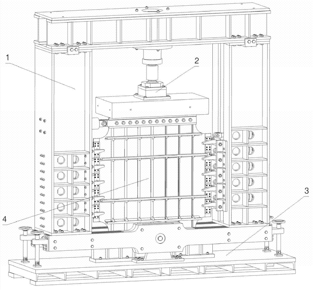
[0031] A test device capable of uniformly applying axial compressive loads and shear loads, such as figure 1 As shown, it includes a shear load application assembly 1 , an axial compression load application assembly 2 , a lower platform assembly 3 and a stiffened plate assembly 4 .

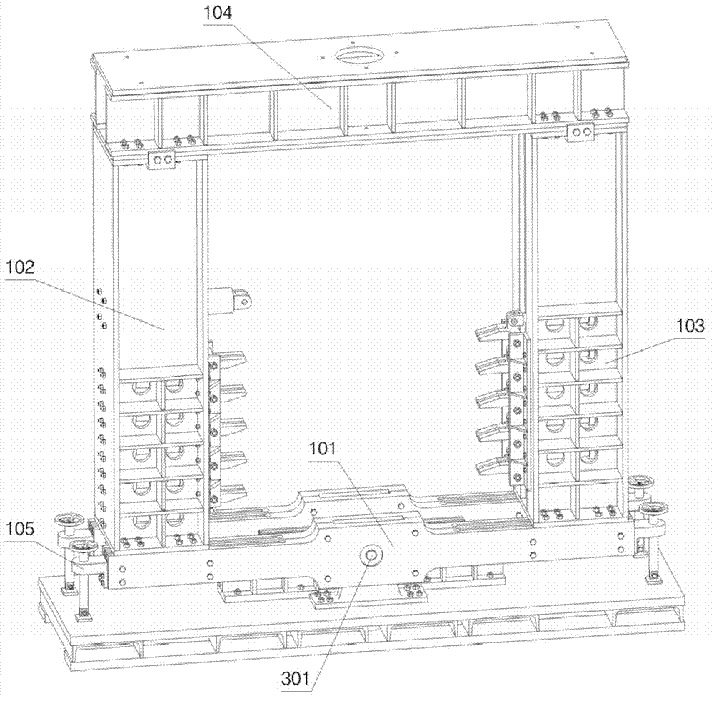
[0032] Such as figure 2 As shown, the shear load application assembly 1 includes a rotating platform 101, a left column assembly 102 and a right column assembly 103 fixed on the rotating platform 101, an upper beam 104, and a leveling device fixed on the rotating platform 101 105, the rotating platform 101 is connected with the lower platform assembly 3 through the large rotating shaft 301;

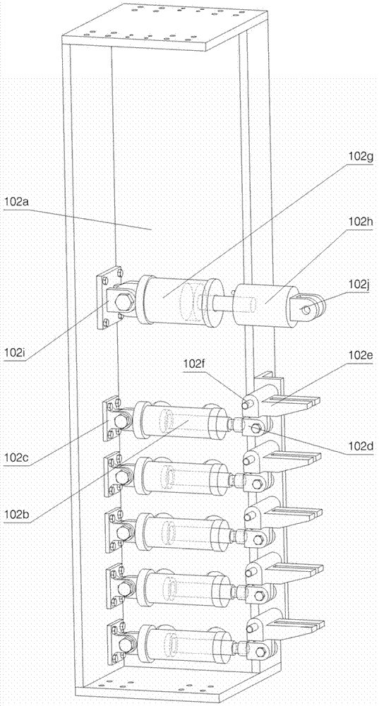
[0033] Such as image 3 , Figure 4 As shown, in order to make the layout of the internal structure clearly visible, part of the structure of the left co...


PUM


Abstract

The invention belongs to the technical field of strength tests in aviation, and particularly relates to a test device capable of evenly applying an axial compression load and a shearing load. The test device comprises a shearing load applying component 1, an axial compression load applying component 2, a lower platform component 3 and a rib-adding flat plate component 4. According to the technology for independently loading the compression load and the shearing load, adopted by the device, the device not only is suitable for the flat plate, but also is suitable for a rib-adding flat plate. Furthermore, the test debugging of the single axial compression load and the single shearing load under the condition that the rib-adding flat plate is invariable in an installing posture can be realized, so that the reference can be provided for the analysis of the stress state of a lower wall plate under the joint action of the compression load and the shearing load. The device applies shearing force by the self-balance principle of a whole frame and a 'load balancer', so that the shearing force can be evenly applied, the axial rigidity of the rib-adding flat plate can not be enhanced due to an adopted segmental shearing reinforcement block, a compression load applying effect can not be influenced, and a 'side frame effect' can be avoided.

Description

technical field [0001] The invention belongs to the technical field of aviation strength testing, in particular to a testing device capable of uniformly applying axial compression and shearing loads. Background technique [0002] Flat plates and stiffened flat plates are typical stressed members in structures such as aerospace vehicles and surface warships. Most of them are in the state of compression and shear composite stress. It is a very important research topic, especially for the research on the stability and strength of the reinforced thin-walled structures that are mostly used in modern aircraft under complex loads. Therefore, it is urgent to realize the loading of such composite loads in the laboratory, so that the designed structure Verifying the stability and strength of the components can also provide a basis for future structural optimization and improvement. [0003] In the past, it was difficult to achieve combined compression-shear loading for this kind of s...

Claims


Application Information

Patent Timeline
IPC IPC(8): G01N3/08G01N3/24
Inventor 柴亚南李崇王力立刘国强
Owner CHINA AIRPLANT STRENGTH RES INST
Why Eureka
Try Eureka