Antenna and multiple input multiple output (MIMO) antenna with same

An antenna and feeder technology, applied in the field of MIMO antennas, can solve problems such as constraints, low operating frequency, and small size of terminal equipment, and achieve high isolation, strong anti-interference ability, and increase the effect of effective radiation area

Active Publication Date: 2013-04-10
KUANG CHI INST OF ADVANCED TECH
View PDF3 Cites 0 Cited by
  • Summary
  • Abstract
  • Description
  • Claims
  • Application Information

AI Technical Summary

Problems solved by technology

Even so, the existing metamaterial small antennas are greatly restricted in the design process when faced with the problems of existing terminal equipment such as small size, low operating frequency, broadband multi-mode, etc.

Method used


Image

  • Antenna and multiple input multiple output (MIMO) antenna with same
  • Antenna and multiple input multiple output (MIMO) antenna with same
  • Antenna and multiple input multiple output (MIMO) antenna with same

Examples


Embodiment Construction

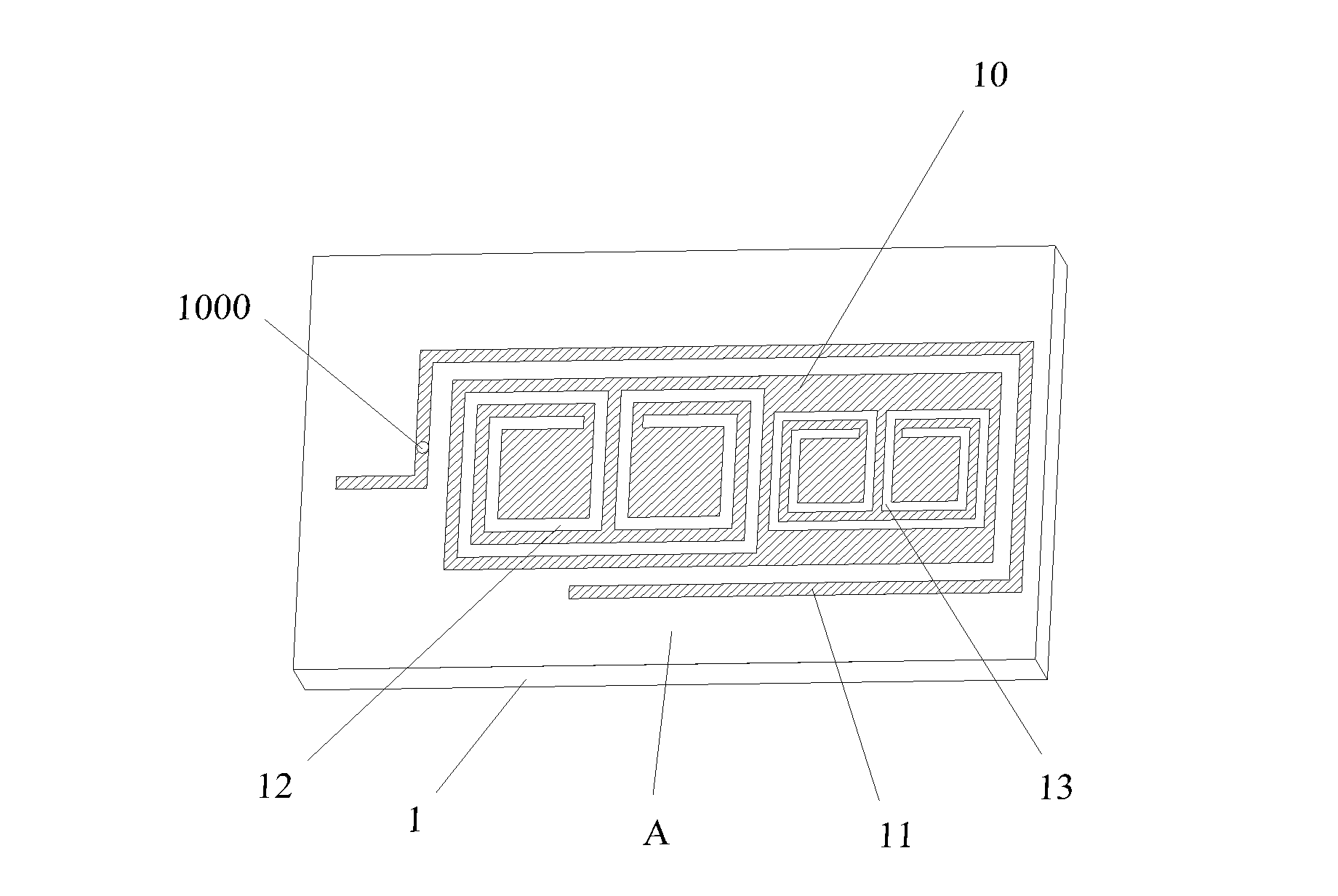
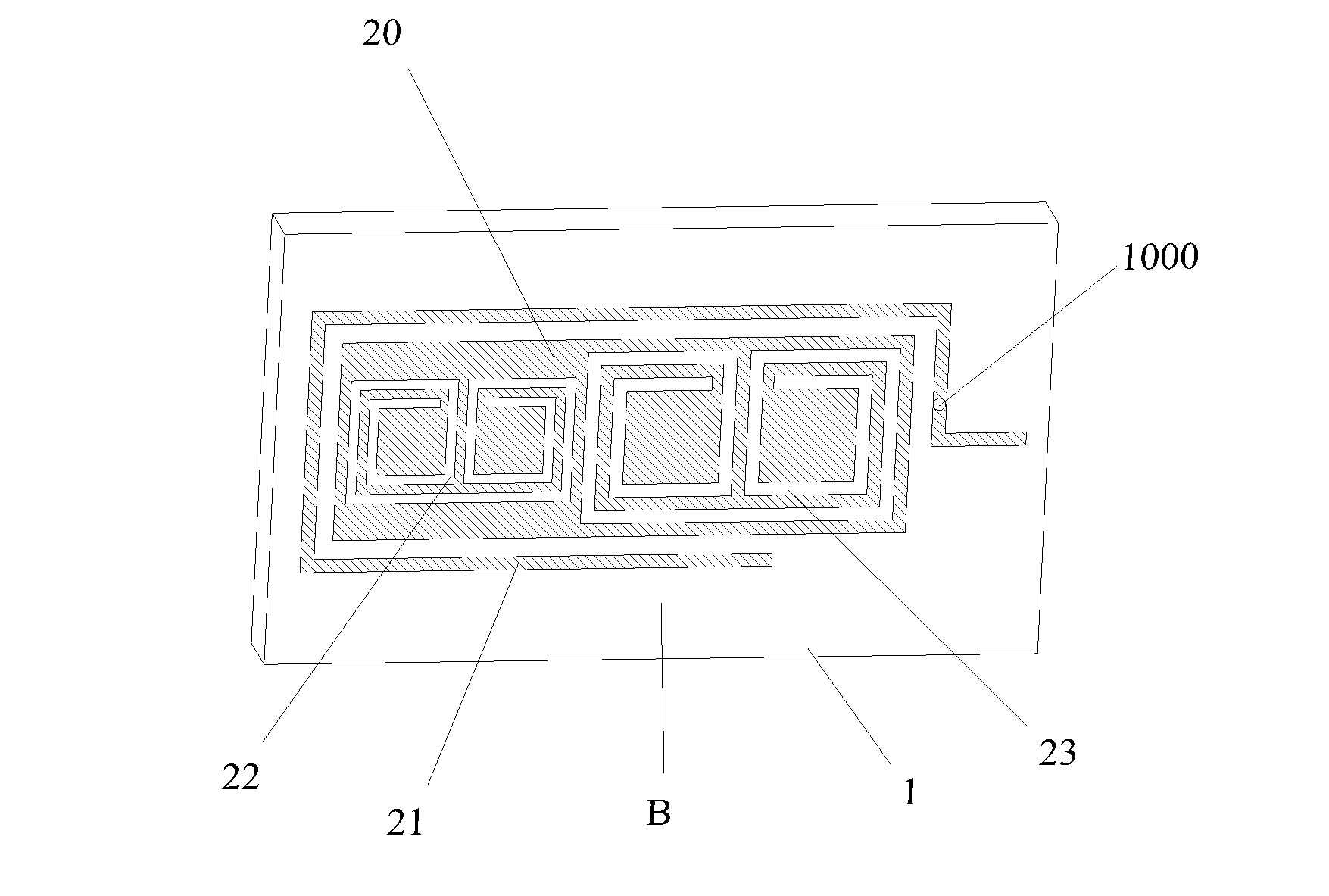
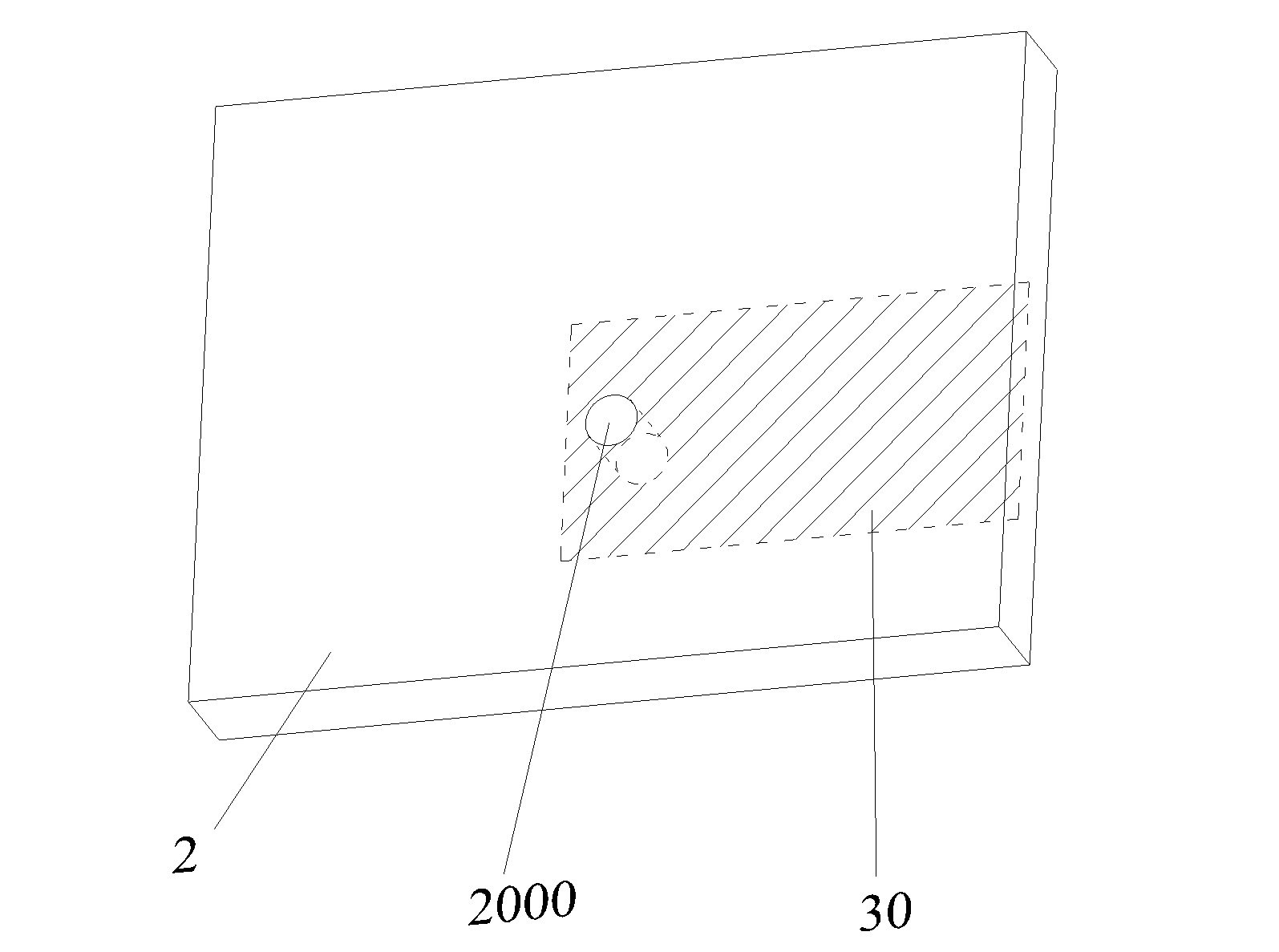
[0032] Such as Figure 1 to Figure 3 As shown, the antenna of the present invention includes a first dielectric substrate 1 and a second dielectric substrate 2, and the first dielectric substrate 1 has a surface A and a surface B opposite to each other. A surface is provided with a first metal sheet 10, a first feeder 11 arranged around the first metal sheet 10, and an asymmetrical first micro-groove structure 12 and a second micro-groove structure 13 are engraved on the first metal sheet 10; B A second metal sheet 20 is arranged on the surface, and a second feeder 21 arranged around the second metal sheet 20 is engraved with an asymmetrical third micro-groove structure 22 and a fourth micro-groove structure 23 on the second metal sheet 20 . Both the first feeder line 11 and the second feeder line 21 are fed into the first metal sheet 10 and the second metal sheet 20 through coupling, and the first feeder line 11 and the second feeder line 21 are electrically connected. The s...


PUM


Abstract

The invention relates to an antenna which comprises a first dielectric substrate and a second dielectric substrate. Metal sheets are arranged on two surfaces of the dielectric substrates, space area of the antenna is used fully, and the antenna can be operated at low operating frequency under the environment and simultaneously meets requirements for miniaturization, low operating frequency and broadband multi-mode. In addition, a multiple input multiple output (MIMO) antenna with a plurality of the antennas is further related. The MIMO antenna has high isolation.

Description

technical field [0001] The invention belongs to the communication field, and in particular relates to an antenna and a MIMO antenna with the antenna. Background technique [0002] In traditional antenna design, when problems such as small antenna space, low operating frequency, and multi-mode operation are encountered, the performance of the antenna will be greatly restricted by the size of the antenna. The electrical length of the antenna corresponding to the reduction of the volume of the antenna will also be affected, and the radiation efficiency and operating frequency of the antenna will change. Traditional dipole antennas and PIFA antennas are powerless when faced with the problems of small size and broadband in existing communication terminals, and the design is extremely difficult and ultimately cannot meet the requirements of use. In the design of traditional antennas in the low frequency band, only external matching lines are used to meet the multi-mode radiation ...

Claims


Application Information

Patent Timeline
Patent Type & Authority Applications(China)
IPC IPC(8): H01Q1/38H01Q5/01H01Q21/00H01Q5/10
Inventor 刘若鹏徐冠雄杨松涛
Owner KUANG CHI INST OF ADVANCED TECH
Why Eureka
Try Eureka