Charging device and charging method

A charging device and charging electrode technology, applied in circuit devices, battery circuit devices, secondary battery charging/discharging, etc., to achieve the effects of less power consumption, small size, and wide voltage regulation range

Active Publication Date: 2015-02-11
ECOVACS ROBOTICS (SUZHOU ) CO LTD
View PDF3 Cites 1 Cited by
  • Summary
  • Abstract
  • Description
  • Claims
  • Application Information

AI Technical Summary

Problems solved by technology

However, the switching power supply circuit also has the shortcoming of continuous working time
The reason is that the switching power supply circuit works under high voltage, and its capacitors and other circuit components are easily broken down and damaged in a long-term high-voltage environment.
Usually, the charging device is connected to the working voltage of 220 volts 24 hours a day, so as to charge the electrical equipment such as robots at any time. Since the switching power supply circuit is not suitable for continuous work for a long time, although people have long recognized that the switching power supply circuit can solve the The problem of fast charging of electrical equipment, and switching power supply circuits have been used in artificial charging devices, but before the present invention, people have not successfully applied switching power supply circuits to automatic and fast charging of electrical equipment such as robots. In the charging device

Method used


Image

  • Charging device and charging method
  • Charging device and charging method
  • Charging device and charging method

Examples


Embodiment 1

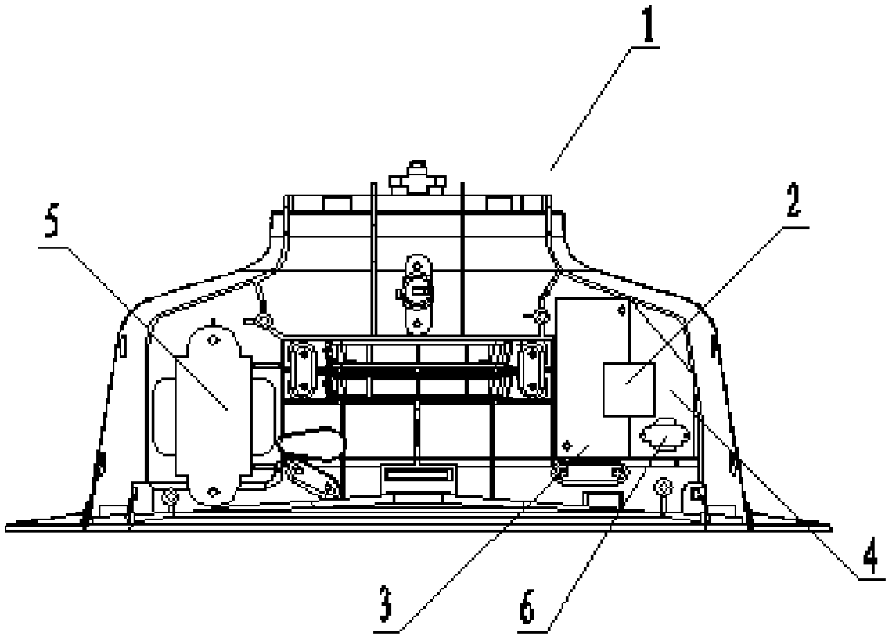
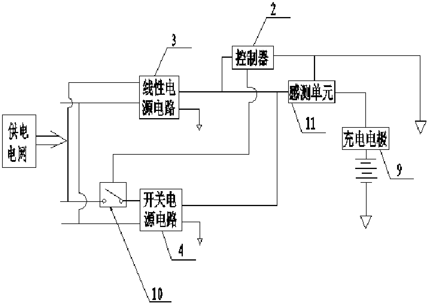
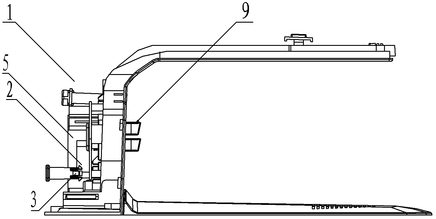
[0046] Such as figure 1 , figure 2 , image 3 , Figure 4 , Figure 5 , Figure 6 As shown, the charging device 1 includes a controller 2, a linear power supply circuit 3 and a charging electrode 9. The charging device 1 also includes a switching power supply circuit 4 connected in parallel with the linear power supply circuit 3. The input and output terminals of the switching power supply circuit 4 are respectively Connected with the first switch 10 and the charging electrode 9, the switching power supply circuit 4 is provided with an inverter 6, which is also called a high-frequency transformer, and its function is to convert direct current into alternating current.

[0047] The output end of the linear power supply circuit 3 is connected to the controller 2, and the linear power supply circuit 3 is provided with a linear transformer 5; the controller 2 controls the connection and disconnection of the switching power supply circuit 4 through the first switch 10.

[00...

Embodiment 2

[0061] In Embodiment 2, the components, circuit connections and working principles included in the charging device 1 are basically the same as those in Embodiment 1. The difference between the two is that in Embodiment 2, the charging device 1 is also provided with a second switch (not shown in the figure), the output end of the linear power supply circuit 3 is connected to the charging electrode 9 through the second switch; when the controller 2 turns off the first switch 10, the second switch is closed.

[0062] The significance of adding the second switch is that when the storage battery of the electric device 7 is fully charged, if the electric device 7 does not need to be put into work immediately, the first switch 10 can be disconnected by the controller 2, and the second switch is closed, thereby The linear power supply circuit 3 supplementally charges the electric device 7 by way of trickle charging, so as to maintain the full power state of the electric device 7 . And...

Embodiment 3

[0066] The difference between this embodiment and embodiments 1 and 2 lies in the connection relationship between the sensing unit and other components. Specifically, in this embodiment, the sensing unit is only connected to the controller 2 and not connected to the charging electrode 9 . Specifically, when the sensing unit adopts an electromagnetic sensor or a magnetic induction sensor, the sensing unit may not be connected to the charging electrode 9 .

[0067] For example, a magnetic signal transmitter can be arranged near the docking electrode 8 of the electrical device 7, and when the docking electrode 8 of the electrical device 7 is docked with the charging electrode 9 of the charging device 1, the magnetic signal sensor can sense the corresponding magnetic signal, and send the sensing signal to the controller 2, and the controller 2 controls the first switch 10 to turn off according to the sensing signal.

[0068] As another example, an electromagnetic sensor can also ...


PUM


Abstract

The invention discloses a charging device and a charging method. The charging device comprises a controller, a linear power supply circuit and charging electrodes. The charging device further comprises a switch power supply circuit which is in parallel connection with the linear power supply circuit, wherein an input end and an output end of the switch power supply circuit are respectively connected with a first switch and the charging electrodes, an output of the linear power supply circuit is connected with the controller, and the controller controls a connecting and a disconnecting of the switch power supply circuit through the first switch. The charging device is further provided with sensing units which are respectively connected with the controller and the charging electrodes, when the charging electrodes are connected with a charging apparatus in a butt joint mode, the sensing units generate induce and send a sensing signal to the controller, and the controller controls the disconnecting and the connecting of the first switch according to the sensing signal. According to the fact that the linear power supply circuit supplies power to the charging device controller and the switch power supply circuit supplies power to electric equipments such as a robot, quick charge problem of electric equipments such as a robot is resolved efficiently.

Description

technical field [0001] The invention relates to a charging device and a charging method thereof, in particular to a charging device and a charging method capable of automatically and quickly charging electric equipment such as a robot. [0002] Background technique [0003] Robots and other electrical equipment, such as smart vacuum cleaners, usually rely on their own batteries for power supply. Due to the limited power of the battery, the control system, drive device, and mechanical device that directly executes the work tasks of robots and other electrical equipment are working. Power consumption is required during the process. Therefore, after one charge, the electric device usually does not work for a long time before it needs to be charged again. Previously, the charging of electrical equipment was done manually. Although the method of manual charging can solve the charging problem of electric equipment, it is not conducive to saving human resources. Especially when t...

Claims


Application Information

Patent Timeline
Patent Type & Authority Patents(China)
IPC IPC(8): H02J7/00H01M10/44
CPCY02E60/10
Inventor 汤进举
Owner ECOVACS ROBOTICS (SUZHOU ) CO LTD
Why Eureka
Try Eureka