
Three-phase online power-obtaining device for distribution networks

A technology of energy harvesting device and power distribution network, which is applied in the direction of converting irreversible AC power input into DC power output, etc., which can solve the problems of impossible design of power supply power, large influence of capacitor voltage division ratio, power supply collapse, etc. Achieve self-protection and protection of back-end electronic equipment, high reliability, and the effect of protecting itself and the back-end circuit

Inactive Publication Date: 2013-04-10
WASION GROUP HLDG
View PDF4 Cites 11 Cited by
  • Summary
  • Abstract
  • Description
  • Claims
  • Application Information

AI Technical Summary

Problems solved by technology

However, this simple capacitor voltage division method directly connects the electronic circuit load and the voltage dividing capacitor in parallel, so that the change of the electronic circuit load has a greater impact on the capacitor voltage division ratio, which constitutes a contradiction between the load impedance and the energy supply efficiency. , in the case of severe load fluctuations, it may even directly lead to the collapse of the power supply, which also determines that the power supply in this way cannot be designed to be very large
When a unit with high energy consumption is installed in the online monitoring device, such as a wireless GPRS communication module, this simple voltage energy acquisition method often cannot meet its energy consumption requirements

Method used


Image

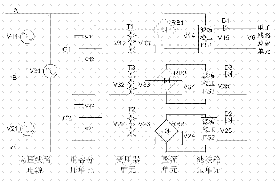
  • Three-phase online power-obtaining device for distribution networks
  • Three-phase online power-obtaining device for distribution networks
  • Three-phase online power-obtaining device for distribution networks

Examples


Embodiment Construction

[0020] The present invention will be further described below in conjunction with the accompanying drawings.

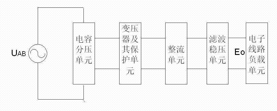
[0021] like figure 1 As shown, the present invention directly obtains electric energy from the high-voltage power line of the power distribution network, and after capacitor voltage division, transformer step-down, rectification and filtering, it is used by load units of electronic equipment such as on-line metering and monitoring.

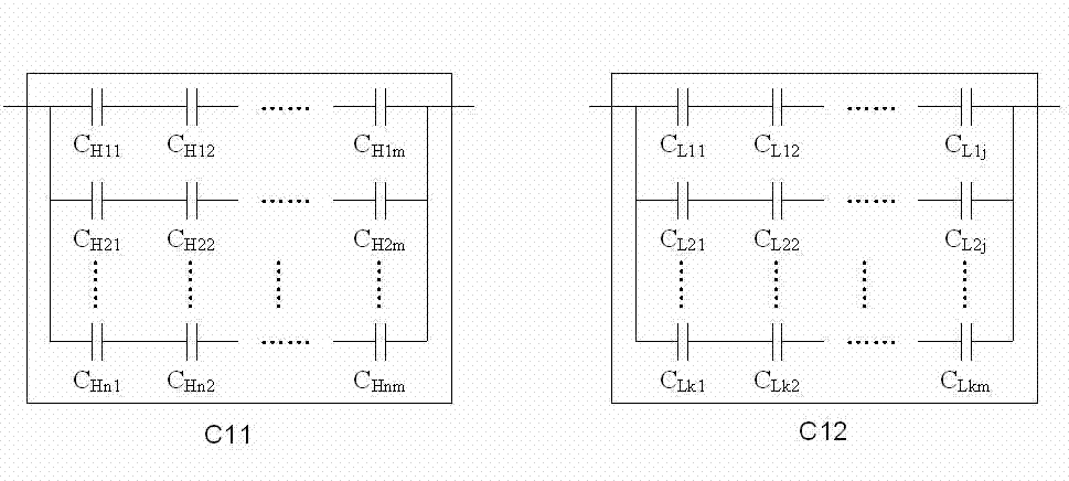
[0022] The high-voltage capacitor unit is a combination of single or multiple high-voltage capacitors in series and parallel, and the low-voltage capacitor unit is a combination of single or multiple low-voltage capacitors in series and parallel. The transformer unit includes a transformer body and an overvoltage and overcurrent protection unit. The capacity of the transformer body is designed and realized according to the energy required for the normal operation of the online electronic equipment load unit and the efficiency of the transf...


PUM


Abstract

The invention discloses a three-phase online power-obtaining device for distribution networks. The three-phase online power-obtaining device for distribution networks comprises two capacitive voltage dividing units, three transformer units, three rectifier units, three filtering stabilivolt units and a electronic equipment load unit. The two capacitance dividing units are respectively connected between A phase and B phase and between B phase and C phase in a bridge connection. Three transformer units are respectively connected in parallel with two low voltage capacitor units. Three outputs of the three transformer units are respectively connected with three rectifier units one to one. The three filtering stabilivolt units are connected with direct current outputs of the three rectifier units one to one. Positive pole outputs of the three filtering stabilivolt units are first respectively connected in series with three protection diode, and then connected in parallel. Negative pole outputs of the three filtering stabilivolt units, after being directly connected in parallel, provide direct power for the electronic equipment load unit. The three-phase online power-acquiring device for distribution networks is capable of providing power above level W and ensures that the provided power is still capable of ensuring normal working of an online electronic equipment load unit when faulty situation of breaking of a single phrase occurs.

Description

technical field [0001] The invention relates to a three-phase on-line energy harvesting device used in a power distribution network. Background technique [0002] At present, the existing online energy harvesting devices for three-phase high-voltage electricity can be roughly divided into two categories: high-voltage current energy harvesting devices and high-voltage voltage energy harvesting devices. High-voltage current energy acquisition uses current energy acquisition coils to obtain current and convert it into energy through the alternating magnetic field generated by inductive load current. However, this method is greatly affected by the load of the line, and it is difficult to ensure the normal operation of the electronic unit. High-voltage voltage energy acquisition generally adopts the method of capacitive voltage division. A voltage-dividing capacitor bank is set to convert the high voltage of the line into low-voltage AC voltage, and after rectification, it is co...

Claims


Application Information

Patent Timeline
Patent Type & Authority Applications(China)
IPC IPC(8): H02M7/06
Inventor 陈金玲王何平易文明易龙强扶小飞
Owner WASION GROUP HLDG
Learn More