HID (High Intensity Discharge) lamp electronic ballast with plurality of protection functions and pre-exciting method thereof
An electronic ballast and protection function technology, applied in the field of high-pressure gas discharge lamp electronic ballasts, can solve the problems of no embodiment of the low-frequency ignition method, not starting the main circuit current, air leakage of the lamp tube, etc., and achieves the component parameters. Low sensitivity, reduced ignition voltage, low starting voltage effect
- Summary
- Abstract
- Description
- Claims
- Application Information
AI Technical Summary
Problems solved by technology
Method used
Image
Examples
Embodiment 1
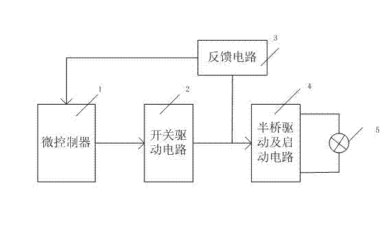
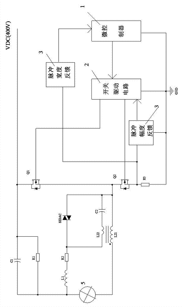
[0034] Such as figure 2As shown, the microcontroller 1 and the switch drive circuit 2 are controlled by the current pulse width and amplitude detection circuit in the feedback circuit 3 respectively. When the lamp is not started, the power switch tube Q2 is turned on and Q1 is turned off, and the power supply VDC charges the capacitor C2 through the resistor R1, inductor L1, resistor R2, inductor L22, power switch tube Q2 and resistor R3; when the voltage on the capacitor C2 exceeds When the trigger voltage of the silicon two-terminal element SIDAC, the silicon two-terminal element SIDAC breaks down, the electric energy on the capacitor C2 generates a reverse electromotive force on the inductor L22 through the breakdown of the silicon two-terminal element SIDAC; due to the turn of the inductor L22 and the main inductor L21 It is relatively large, so the induced high voltage is generated on the main inductor L21 and finally applied to both ends of the HID lamp 5; when the HID ...
Embodiment 2
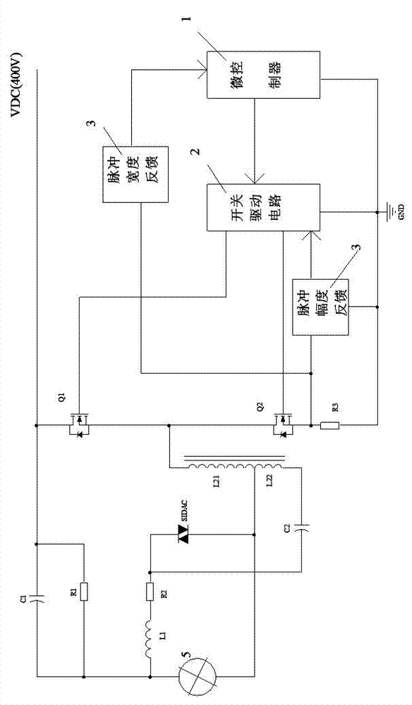
[0043] Such as image 3 with Figure 7 As shown, compared with Embodiment 1, the self-coupling inductors L21 and L22 are changed. In this example, the inductors with a center tap are used as the autocoupling inductors L21 and L22. The specific connection method of the circuit is as follows: capacitor C1 and resistor R1 are connected in parallel, one end of the parallel connection is connected to one end of inductor L1 and one end of HID lamp 5, and the other end is connected to VDC; one end of the inductor L21 is connected to one end of inductor L22, and the silicon two-terminal element One end of the SIDAC is connected to one end of the lamp 5, the other end of the inductor L21 is connected to one end of the power switch tube Q1 and one end of the power switch tube Q2, the other end of the inductor L22 is connected to one end of the capacitor C2, and the other end of the silicon two-terminal element SIDAC One end is connected to the other end of the resistor R2 and the other...
Embodiment 3
[0045] Such as Figure 4 with Figure 8 As shown, compared with Embodiment 2, the ignition trigger device is changed, and the silicon two-terminal element SIDAC trigger is replaced by a thyristor trigger circuit. The thyristor trigger circuit includes: capacitor C21, resistor R4, resistor R5, low-voltage silicon two-terminal element D303, and thyristor SCR. The working principle of the circuit ignition trigger is as follows: when the ignition circuit is working, VDC forms a loop through resistors R1, R2, R3, R4, R5, inductors L1, L21 and power switch tube Q2, when the voltage on resistor R5 exceeds the trigger voltage of D303 ( 28V~32V), D303 is turned on, thereby triggering the thyristor SCR, that is, replacing the function of the silicon two-terminal element SIDAC in Embodiment 2. Other parts of the working principle are the same as in Embodiment 2.
PUM
 Abstract
Description
Claims
Application Information
 - R&D
- Intellectual Property
- Life Sciences
- Materials
- Tech Scout
- Unparalleled Data Quality
- Higher Quality Content
- 60% Fewer Hallucinations
Browse by: Latest US Patents, China's latest patents, Technical Efficacy Thesaurus, Application Domain, Technology Topic, Popular Technical Reports.
© 2025 PatSnap. All rights reserved.Legal|Privacy policy|Modern Slavery Act Transparency Statement|Sitemap|About US| Contact US: help@patsnap.com


