Overlapped turbine type bead separator of medium stirring mill

A turbine type, stirring mill technology, applied in grain processing and other directions, can solve the problems of heat-sensitive material grinding limitation, separation device failure, grinding efficiency reduction, etc. smooth effect

Active Publication Date: 2013-04-17
深圳市叁星飞荣机械有限公司
View PDF8 Cites 10 Cited by
  • Summary
  • Abstract
  • Description
  • Claims
  • Application Information

AI Technical Summary

Problems solved by technology

resulting in reduced grinding efficiency
Although the pipe network static separation method can increase the discharge space according to the increase of the diameter of the pipe network or the length of the pipe network, due to the static discharge method, when encountering a slurry with high viscosity or high consistency, the viscous The material will block the mesh due to adhesion, making the separation device ineffective
Due to the low discharge efficiency of the original two separation methods and the repeated grinding of the materials retained in the grinding chamber, the temperature of the slurry in the grinding chamber is too high, which limits the grinding of some heat-sensitive materials.

Method used


Image

  • Overlapped turbine type bead separator of medium stirring mill
  • Overlapped turbine type bead separator of medium stirring mill

Examples


Embodiment Construction

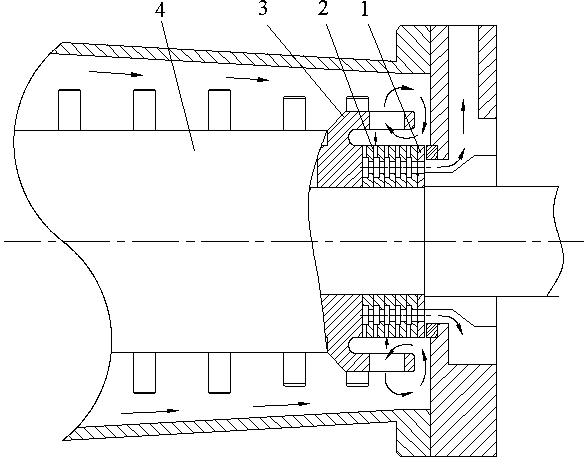
[0012] In order to better understand the present invention, the present invention will be further described below in conjunction with the accompanying drawings. Such as figure 1 As shown, the stacked turbine type high-efficiency bead separator of the present invention includes: a static ring 1, a stacked turbine combination 2 and an outer turbine 3. The static ring 1 is mounted on the end plate of the grinding chamber, the outer turbine 3 and the stirring rotor are installed together, the left end of the stacked turbine group 2 is closely attached to the outer turbine 3, and the right end is placed on the shoulder of the shaft to keep an appropriate distance with the static ring 1. Discharge gap (adjustable). The size of the gap depends on the viscosity of the slurry to be ground, the diameter of the grinding beads and the output requirements.

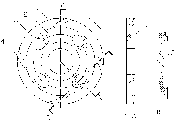
[0013] Such as figure 2 As shown, the turbine lamination set described in the present invention has the same size and structu...


PUM


Abstract

The invention relates to an overlapped turbine type bead separator of a medium stirring mill. The overlapped turbine type bead separator comprises a static ring, an overlapped turbine set and an outer turbine, wherein the static ring is inlaid in the side of a discharging chamber wall, close to a grinding chamber; each turbine blade is provided with a plurality of vortex chutes, a plurality of inclined holes and an annular diversion trench, which are all communicated with one another. One side of the overlapped turbine set clings to the outer turbine, and the other side of the overlapped turbine set is separated from the static ring to form a proper annular discharging clearance; and when a rotor and the turbine set are driven by a main shaft to rotate, the vortex chutes among laminations generate a centripetal absorption force for driving slurry to enter the annular diversion trench, and the inclined holes arranged in the annular diversion trench are used for driving the slurry to be discharged from a discharging hole along the axial direction. Beads are radially thrown away and do radial circulated motion under the action of a centrifugal force generated when the outer turbine rotates, so that the beads are prevented from being accumulated around the bead separator, and the discharge of materials can not be blocked. The overlapped turbine type bead separator is low in manufacturing cost; by using the overlapped turbine type bead separator, the grinding efficiency is greatly increased and the granularity of particles in primarily-ground slurry is remarkably reduced; and compared with the traditional product of the same type, the overlapped turbine type bead separator can be used for increasing the yield by 50-130%.

Description

technical field [0001] The invention belongs to the field of media stirring and grinding equipment, in particular to a stacked turbine type high-efficiency bead separator for a media stirring mill. Background technique [0002] At present, the conventional media stirring mill bead separation devices mainly include dynamic and static ring dynamic separation methods and pipe network static separation methods, which are widely used in coatings, inks, dyes, mining, biology, medicine, and electronic materials. In the field of fine grinding. The dynamic and static ring separation method only forms an annular discharge gap between the dynamic ring and the static ring. Due to the limited discharge space, under the action of the feed pump, many grinding beads accumulate around the separator and rub against each other to generate a large amount of heat. The temperature of the slurry rises and at the same time blocks the discharge of the material. Resulting in reduced grinding effici...

Claims


Application Information

Patent Timeline
Patent Type & Authority Applications(China)
IPC IPC(8): B02C17/18B02C23/08
Inventor 谢小飞
Owner 深圳市叁星飞荣机械有限公司
Why Eureka
Try Eureka