Face shovel excavation device for optimizing lifting force of movable arm

A technology of working device and lifting force, which is applied in the direction of mechanically driven excavators/dredgers, etc., to achieve the effects of easy motion analysis, easy design and analysis, and uniform force distribution

Inactive Publication Date: 2013-04-17
YANSHAN UNIV
View PDF6 Cites 4 Cited by
  • Summary
  • Abstract
  • Description
  • Claims
  • Application Information

AI Technical Summary

Problems solved by technology

Although the front shovel hydraulic excavator technology of foreign manufacturers is relatively mature, their product structure is relatively simple, and the problem of large energy consumption due to small driving force arm has not been solved.

Method used


Image

  • Face shovel excavation device for optimizing lifting force of movable arm
  • Face shovel excavation device for optimizing lifting force of movable arm
  • Face shovel excavation device for optimizing lifting force of movable arm

Examples


Embodiment 1

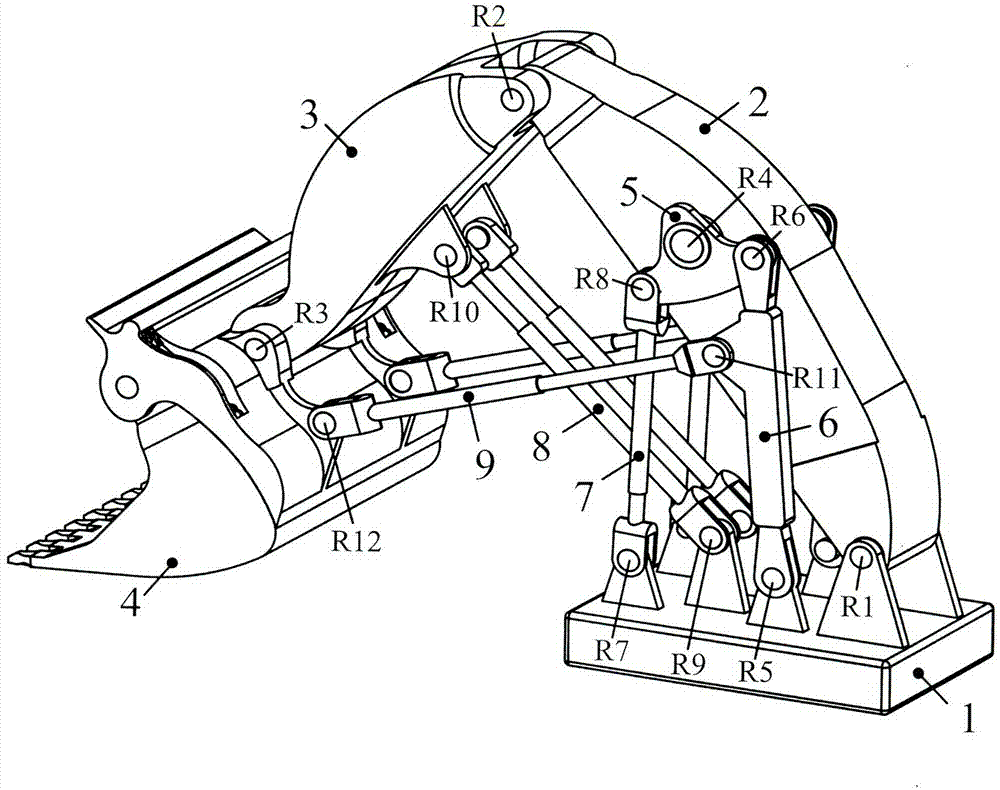
[0027] like figure 1 As shown, the frame 1 of the present invention is hinged to the lower end of the boom 2 through the hinge R1, the upper end of the boom 2 is hinged to one end of the arm 3 through the hinge R2, and the other end of the arm 3 is hinged to the bucket 4 through the hinge R3. A part of the hinge. A pair of boom rockers 5 are symmetrically hinged on both sides of the middle part of the boom 2 through hinges R4, and the pair of boom rockers 5 are respectively hinged with one end of a pair of frame connecting rods 6 through hinges R6. The other end of the frame connecting rod 6 is hinged with the frame through the hinge R5. The cylinder liner ends of a pair of boom hydraulic cylinders 7 are respectively hinged to another part of the boom rocker 5 through the hinge R8, and the piston rod ends of the pair of boom hydraulic cylinders 7 are hinged to the frame through the hinge R7; The cylinder liner ends of a pair of stick hydraulic cylinders 8 are respectively h...

Embodiment 2

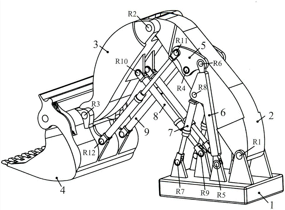
[0029] like figure 2 As shown, one end of the frame 1 of the present invention is hinged to the lower end of the boom 2 through the hinge R1, the upper end of the boom 2 is hinged to one end of the arm 3 through the hinge R2, and the other end of the arm 3 is hinged to the shovel through the hinge R3. A part of bucket 4 is hinged. A pair of boom rockers 5 are symmetrically hinged on both sides of the middle part of the boom 2 through the hinge R4 respectively. The pair of boom rockers 5 are respectively hinged with one end of the pair of frame connecting rods 6 through the hinge R6, and the other ends of the pair of frame connecting rods 6 are respectively hinged with the frame 1 through the hinge R5; the pair of boom hydraulic pressure The ends of the cylinder sleeves of the cylinder 7 are respectively hinged to the middle part of the frame connecting rod 6 through the hinge R8, and the piston rod ends of the pair of boom hydraulic cylinders 7 are respectively hinged to the...

Embodiment 3

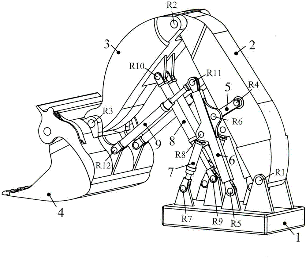
[0031] like image 3 As shown, one end of the frame 1 of the present invention is hinged to the lower end of the boom 2 through the hinge R1, the upper end of the boom 2 is hinged to one end of the arm 3 through the hinge R2, and the other end of the arm 3 is hinged to the shovel through the hinge R3. A part of bucket 4 is hinged. One end of a pair of boom rockers 5 is symmetrically hinged on both sides of the middle part of the boom 2 through a hinge R4, and the other end of the pair of boom rockers 5 is respectively connected to a pair of frame connecting rods 6 through a hinge R6. One part is hinged, and one end of the pair of frame connecting rods 6 is respectively hinged with the frame 1 through the hinge R5; Hinged, the piston rod ends of the pair of boom hydraulic cylinders 7 are hinged with the frame 1 through the hinge R7 respectively; The piston rod ends of the pair of stick hydraulic cylinders 8 are respectively hinged with the frame 1 through the hinge R9; the cy...


PUM


Abstract

The invention discloses a face shovel excavation device for optimizing lifting force of a movable arm. The lower end of the movable arm is hinged with a machine frame, and the upper end of the of the movable arm is hinged with one end of a bucket rod; the other end of the bucket rod is hinged with the upper part of a shovel bucket, and the lower part of the shovel bucket is hinged with one end of a pair of shovel bucket hydraulic cylinders; the middle part of the bucket rod is hinged with one end of a pair of bucket rod hydraulic cylinders, and the other end of the pair of bucket rod hydraulic cylinders is hinged with the machine frame; and one end of a pair of machine frame connecting rods is hinged with the machine frame. The face shovel excavation device is characterized in that one end of a pair of movable arm hydraulic cylinders is hinged with the movable arm through a pair of movable arm rockers, or one end of the pair of movable arm hydraulic cylinders is hinged with the movable arm through the pair of machine frame connecting rods and the pair of movable arm rockers; the other end of the pair of movable arm hydraulic cylinders is hinged with the machine frame; and the other end of the pair of shovel bucket hydraulic cylinders is hinged with the pair of movable arm rockers or the pair of machine frame connecting rods or the movable arm. According to the face shovel excavation device, the stress on all the components is uniformly distributed, the energy consumption is reduced, the lifting force of the movable arm can be optimized, and the face shovel excavation device is compact in structure and has a wide application prospect.

Description

technical field [0001] The invention relates to an excavator, in particular to a working device for a front shovel hydraulic excavator. Background technique [0002] The large-scale front shovel hydraulic excavator is the main tool for mining in open-pit coal mines, and its excavating working device is the main component to complete various functions of the excavator. There are few domestic researches on the working device of the hydraulic front shovel excavator. Chinese patent CN200520035287.8 relates to a horizontal pushing device of a hydraulic excavator front shovel operation device, which is characterized in that the piston rod of the bucket cylinder is hinged to the front end of the boom, the rear part of the stick is hinged to the front end of the boom, and the bucket is hinged to the front end of the stick , the bucket is hinged to the end of the bucket oil cylinder, and the hinge points form a four-bar device with a quadrilateral structure in the air. Chinese pat...

Claims


Application Information

Patent Timeline
Patent Type & Authority Applications(China)
IPC IPC(8): E02F3/36E02F3/42
Inventor 丁华锋陈谊超曹宇徐弓月王怀宝马利
Owner YANSHAN UNIV
Why Eureka
Try Eureka