Control valve of carbon tank

A technology for controlling valves, carbon canisters, applied in the direction of valve details, valve devices, valve operation/release devices, etc.

Active Publication Date: 2013-04-17
UNITED AUTOMOTIVE ELECTRONICS SYST
View PDF8 Cites 2 Cited by
  • Summary
  • Abstract
  • Description
  • Claims
  • Application Information

AI Technical Summary

Problems solved by technology

Existing canister control valves are

Method used


Image

  • Control valve of carbon tank
  • Control valve of carbon tank
  • Control valve of carbon tank

Examples


Embodiment Construction

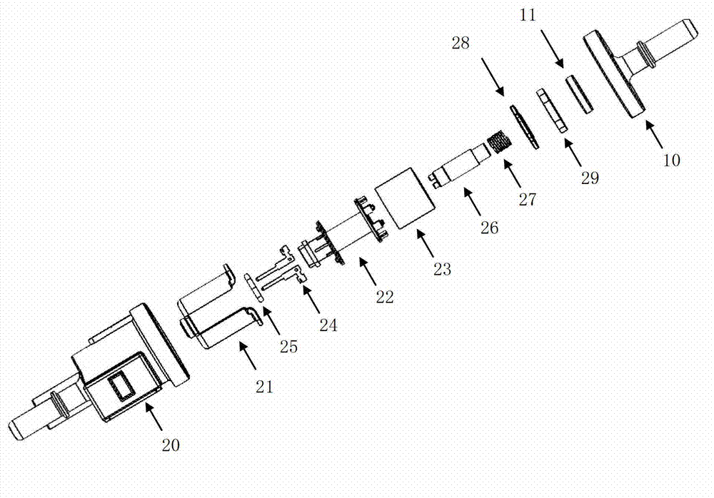
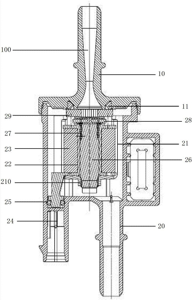
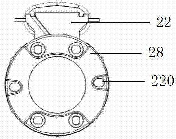
[0022] see figure 1 and figure 2 , which is a specific embodiment of the carbon canister control valve of the present application. The carbon canister control valve includes an upper cover 10 and a housing 20, which are connected to each other by welding and kept sealed. There is a through hole 100 in the shape of a de Laval nozzle in the upper cover 10 . The cross-sectional area of ​​the Laval tube first becomes smaller and then larger, and the gas passing through it can be accelerated. There are two pipelines under the housing 20 , the second pipeline on the right is a gas circulation pipeline, and the first pipeline on the left is used for installing the connector at the lower end of the pin 24 . There is a protrusion on the right side of the housing 20, which is a skeleton for placing rubber supports. The housing 20 has a magnetic tank 21, a coil bobbin 22, a coil 23, pins 24, a magnetic core 26, an armature 28 and Seat 29.

[0023] The magnetic pot 21 is roughly rin...


PUM


Abstract

The invention discloses a control valve of a carbon tank. The carbon tank comprises an upper cover and a shell, wherein the upper cover is provided with a Laval pipe shaped through hole; the shell is internally provided with a magnetic tank, a coil framework, a coil, a contact pin, a magnetic core, armature iron and a valve seat; and the magnetic tank is internally provided with a cavity. The coil framework, the coil and the contact pin are mounted in the cavity; the coil framework is provided with a hollow shaft; the coil is wound at the periphery of the hollow shaft of the coil framework; the contact pin is fixed on the coil framework; a copper line of the coil is electrically connected to one end of the contact pin; the magnetic core is located in the hollow shaft of the coil framework and is fixed with the magnetic tank by screw threads; the armature iron and the valve seat are respectively arranged on the coil framework; a through hole with a radial section is arranged at the center of the valve seat; and a spring is arranged between the magnetic core and the armature iron. By adopting the Laval pipe structure, the control valve of the carbon tank, disclosed by the invention, can overcome a difference of pressures at two ends of the control valve of the carbon tank and realize a relatively steady gas flow.

Description

technical field [0001] This application relates to a canister control valve (TEV) in a gasoline evaporative emission control system. Background technique [0002] The gasoline evaporative emission control system system consists of a canister and a canister control valve. The canister absorbs fuel vapor from the fuel tank until saturated with fuel vapor. The electronic controller controls the control valve of the carbon tank to open, and the fresh air and the saturated fuel vapor in the carbon tank form a regeneration airflow. The regenerative airflow is sucked into the cylinder from the intake pipe to participate in combustion. This system not only reduces emissions by preventing fuel vapor from escaping into the atmosphere, but also reduces fuel consumption. [0003] US Patent No. US4901974A (authorization date: February 20, 1990) discloses a canister control valve, which can basically control the flow of fresh air flowing through the canister control valve, but there is...

Claims


Application Information

Patent Timeline
IPC IPC(8): F16K31/06
Inventor 过于成赵志球汪植亮
Owner UNITED AUTOMOTIVE ELECTRONICS SYST
Why Eureka
Try Eureka