Atomic current sensor

A technology of a current sensor and a temperature sensor, applied in the sensor field, can solve the problem that the electromagnetic sensor cannot meet the requirements well, and achieve the effects of simple structure, long working life and low cost

Active Publication Date: 2013-04-17
CHENGDUSCEON ELECTRONICS
View PDF5 Cites 2 Cited by
  • Summary
  • Abstract
  • Description
  • Claims
  • Application Information

AI Technical Summary

Problems solved by technology

[0004] The present invention provides an atomic current sensor, aiming at overcoming the defect that the use of electromagnetic sensors in the fields of engineering detection of high-precision current detection and current measurement detection cannot well meet the requirements

Method used


Image

  • Atomic current sensor
  • Atomic current sensor
  • Atomic current sensor

Examples


Embodiment 1

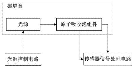
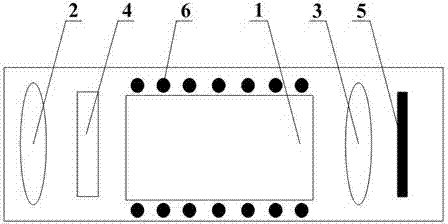
[0042] Such as figure 1 , figure 2 , image 3 , Figure 4 As shown, the atomic current sensor of the present invention completes the signal transmission function by filtering light.

[0043] Such as figure 1 As shown, the electronic current sensor includes a light source control circuit, a light source, an atomic absorption bubble assembly and a sensor processing circuit.

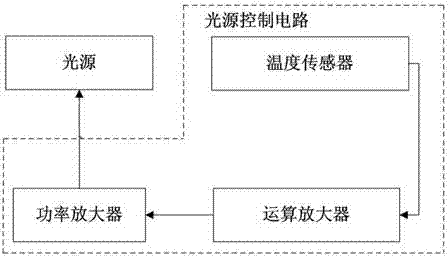
[0044] Such as figure 2 As shown, the light source control circuit is mainly used to sense and amplify voltage, and finally output high-power current. Wherein the temperature sensor on the light source control circuit in this embodiment is preferably a thermistor, and the resistivity of the temperature sensor changes with the change of temperature, so according to the change of the resistivity, the magnitude of the voltage loaded on it is constantly changing, and the voltage is passed through the operational amplifier. After amplification, the current is continuously amplified through the power ampl...

Embodiment 2

[0057] The difference from Embodiment 1 is that in order to better realize the present invention, this embodiment additionally sets a laser cover on the laser tube to keep the temperature of the laser tube constant. Since the laser tube itself will generate heat, the light source control circuit The thermistor is set in the laser cover, and the heating temperature of the power amplifier is controlled by feedback according to the temperature in the laser cover, which can better ensure that the frequency of the laser emitted by the laser tube remains constant and improve the filtering accuracy.

Embodiment 3

[0059] The difference from Example 1 is that, as Figure 5 As shown, the sensor signal processing circuit includes a band-pass amplifier and a 90° phase shifter. The band-pass amplifier is connected with the photocell in the atomic absorption bubble assembly, and the output signal of the photocell is shifted by 90°. The 90° phase shifter has There are two output terminals: one of the output terminals outputs a signal to the coupling coil for signal feedback, and controls the coupling coil to generate a magnetic field; the output signal of the other output terminal is the signal output by the atomic current sensor. At this point, the present invention has completed its function.

[0060] Among them, the signal processing method performed by the sensor signal processing circuit is called active type.


PUM


Abstract

The invention discloses an atomic current sensor, which belongs to the field of electronics. The atomic current sensor comprises a light source control circuit, a light source, an atom absorption foam assembly and a sensor signal processing circuit, wherein the light source is controlled by using the light source control circuit; the atom absorption foam assembly is used for receiving an optical signal transmitted by the light source; and the sensor signal processing circuit interacts with the atom absorption foam assembly. Through the setting, the defect that an electromagnetic sensor applied in the fields of engineering detection of high-accuracy current detection, current metering detection and the like cannot well met requirements is overcome; and the atomic current sensor is simple in structure, has high measuring accuracy, and is suitable for popularizing and using.

Description

technical field [0001] The invention relates to a sensor, in particular to an atomic current sensor. Background technique [0002] Most of the existing sensors are electromagnetic sensors. The existing electromagnetic sensors use magnetoelectric induction to measure the speed of objects, and convert magnetic signals into electrical signals for output. They belong to non-contact speed measuring instruments, so they are also called electromagnetic sensors. current sensor. Electromagnetic sensors are among the most widely used sensors on the market today. [0003] However, due to the characteristics of low measurement accuracy and easy to be affected by the environment, the electromagnetic sensor cannot satisfy the fields of engineering detection and current measurement detection of high-precision current detection. Contents of the invention [0004] The invention provides an atomic current sensor, aiming at overcoming the defect that the electromagnetic sensor cannot well ...

Claims


Application Information

Patent Timeline
Patent Type & Authority Applications(China)
IPC IPC(8): G01R19/00
Inventor 曹远洪
Owner CHENGDUSCEON ELECTRONICS
Why Eureka
Try Eureka