Processing method and device of delay between signals

A delay processing and inter-signal technology, applied in the field of communication, can solve problems such as incorrect data demultiplexing results, achieve the effect of solving incorrect data demultiplexing results, high accuracy, and improving the accuracy of data decoding

Inactive Publication Date: 2013-04-17
ZTE CORP
View PDF6 Cites 11 Cited by
  • Summary
  • Abstract
  • Description
  • Claims
  • Application Information

AI Technical Summary

Problems solved by technology

[0007] Aiming at the problem that the delay between signals leads to incorrect data demultiplexing results, the present invention provides a delay processing method and device between signals to solve this problem

Method used


Image

  • Processing method and device of delay between signals
  • Processing method and device of delay between signals
  • Processing method and device of delay between signals

Examples


Embodiment 1

[0051] This preferred embodiment provides a method for adjusting a non-integer multiple delay between symbols, and the method includes the following steps S302 to S310.

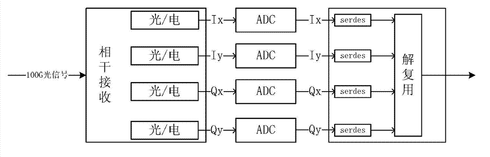
[0052] Step S302: The multiple electrical signals generated through coherent reception are sent to the ADC for sampling, and each electrical signal corresponds to an ADC.

[0053] Step S304: The digital signals sampled by the multi-channel ADCs are sent to the multi-channel serdes for data serial-to-parallel conversion and clock recovery.

[0054] Step S306: Forcibly lock a clock recovery unit (Digital Clock Recovery, CDR for short) of the serdes to a reference clock of the same source as the ADC output data. The CDR of serdes recovers two clocks: a high-speed recovery clock, the clock frequency is half of the serdes rate, which is used to sample the serial input data of the serdes; a low-speed recovery clock, the clock frequency is the same as the rate of the serdes and parallel It is related to the data bi...

Embodiment 2

[0067] This preferred embodiment provides a non-integer multiple delay alignment method for multi-channel data after coherent reception of 100GE services, Figure 8 It is a schematic diagram of a multi-channel data delay alignment method after coherent reception of 100GE services according to an embodiment of the present invention, as shown in Figure 8 As shown, the 100GE signal is sent to the ADC for 1.5 times sampling of the I-channel and Q-channel signals of polarization states X and Y generated by coherent reception, and the signal sampled by each ADC channel is sent to a multi-channel serial-to-parallel converter for conversion and In this process, the CDR of the serdes is forced to lock on the reference clock with the same source as the ADC output data, and the phase interpolation is performed on the high-speed clock recovered by the CDR of each serdes channel, that is, the high-speed clock is adjusted within one clock unit. The sampling position of the row input data, ...

Embodiment 3

[0075] This preferred embodiment provides a method for delay alignment of multi-channel data after coherent reception of OTU4 services, Figure 9 It is a flow chart of the multi-channel data delay alignment method after the OTU4 service is coherently received according to the embodiment of the present invention, as shown in Figure 9 as shown in Figure 9As shown, the OTU4 service signal is sent to the ADC for 1.5-fold sampling of the polarization states X and Y of the I-channel and Q-channel signals generated by coherent reception, and the signal sampled by each ADC channel is sent to a multi-channel serial-to-parallel converter for conversion. And recovery, in this process, the CDR of serdes is forced to lock on the reference clock with the same source as the ADC output data, and the phase interpolation is performed on the high-speed clock recovered by the CDR of each serdes channel, that is, the high-speed clock pair is adjusted within one clock unit The sampling position ...


PUM


Abstract

The invention discloses a processing method and device of a delay between signals. The processing method comprises the following steps of: determining an error rate of each of multiple paths of serial digital signals in N sampling clocks, wherein each sampling clock in the N sampling clocks is the sum of a recovery clock and N interpolating phases, and the N interpolating phases are preset in a clock unit; determining the interpolating phase corresponding to each path of serial digital signal according to the error rate, wherein the position of each sampling clock is preset in a clock unit; and adjusting a clock of each path of serial digital signal by using the interpolating phase corresponding to each path of serial digital signal. According to the processing method and device disclosed by the invention, the data transmission reliability is improved.

Description

technical field [0001] The present invention relates to the communication field, in particular to a method and device for processing delay between signals. Background technique [0002] Network and aggregation are the main driving forces for the development of 100G and beyond 100G. Increasing the aggregation capacity can meet the ever-increasing business demands. [0003] At present, the 40G optical transmission system mainly adopts the self-coherent receiving mode, which limits the application of polarization multiplexing technology. In order to improve the transmission performance, the 100G optical transmission system adopts the Polarization Multiplexed-Differential Quadrature Reference Phase Shift Keying (PM-DQPSK) modulation method, and the transmitting end is divided into polarization multiplexing and DQPSK There are two parts of modulation, and the receiving end is divided into two parts: polarization demultiplexing and differential quadrature reference phase shift ke...

Claims


Application Information

Patent Timeline
Patent Type & Authority Applications(China)
IPC IPC(8): H04L1/00
CPCH04L1/203H04L7/0025H04L7/0054H04B10/614H04B10/6162H04L7/0016H04L7/0075
Inventor 孟英
Owner ZTE CORP
Why Eureka
Try Eureka