FPGA (Field Programmable Gate Array)-based pulse wave signal generator and method

A signal generator and signal generation technology, applied in catheters and other directions, can solve the problems of limited function, inconvenient use, etc., achieve fast running speed, simple operation, and solve the effects of system function defects

Active Publication Date: 2013-04-24
NORTHEASTERN UNIV
View PDF3 Cites 14 Cited by
  • Summary
  • Abstract
  • Description
  • Claims
  • Application Information

AI Technical Summary

Problems solved by technology

[0003] Another example is the utility model patent "Digital Pulse Wave Signal Generator" with the patent No. 200720103587.1, which uses a single-chip microcomputer as a processor to generate pulse waves and is used as a pulse wave instrument detection device. However, this patent can only be connected to a PC. , through the USB data cable, download the pulse wave data in the PC to the EPROM, display the waveform through the LCD and the oscilloscope, and simply achieve the function of displaying the waveform. A large amount of pulse wave data needs to be known to make the device achieve its function. , which limits the role of the digital pulse wave signal generator in detecting pulse wave instruments
[0004] In addition, there are some signal generators that can only output simple signals such as sine waves and square waves. There are also some pulse wave signal generators that can only display the final waveform if the complete pulse wave data is stored in the computer. Obviously this gives us Normal use brings a lot of inconvenience

Method used


Image

  • FPGA (Field Programmable Gate Array)-based pulse wave signal generator and method
  • FPGA (Field Programmable Gate Array)-based pulse wave signal generator and method
  • FPGA (Field Programmable Gate Array)-based pulse wave signal generator and method

Examples


Embodiment Construction

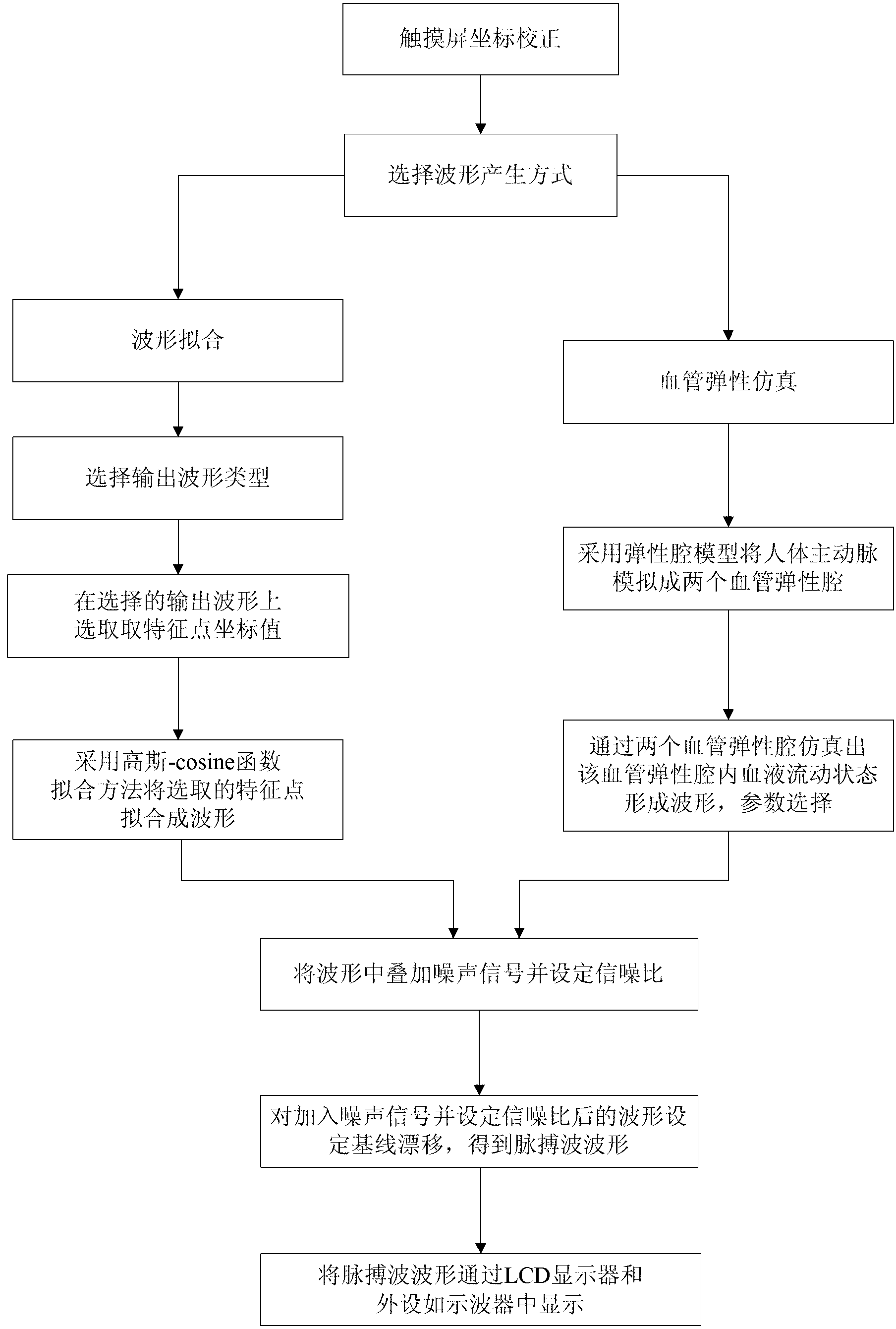
[0064] The specific implementation manners of the present invention will be described in detail below in conjunction with the accompanying drawings.

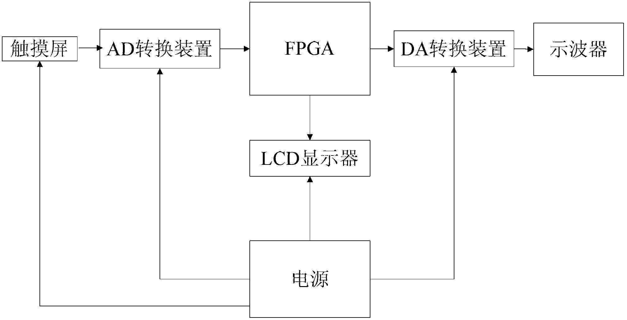
[0065] Such as figure 1 As shown, the pulse wave signal generator based on FPGA includes touch screen, LCD display, oscilloscope, FPGA, power supply, AD conversion device and DA conversion device;

[0066] The power supply is used to supply power for LCD display, touch screen, AD conversion device and DA conversion device;

[0067] The AD conversion device is used to convert the voltage value generated by clicking the touch screen into a coordinate digital value and transmit the coordinate digital value to the FPGA;

[0068] The DA conversion device is used to convert the digital waveform output by the FPGA into an analog waveform and transmit the analog waveform to the oscilloscope;

[0069] FPGA is used to generate pulse wave signal and transmit it to LCD display or oscilloscope for pulse wave waveform display;

[0070] The...


PUM


Abstract

The invention discloses an FPGA (Field Programmable Gate Array)-based pulse wave signal generator comprising an LCD (Liquid Crystal Display), an oscilloscope, an FPGA, a touch screen, a power supply, an AD (Analog-to-Digital) conversion device and a DA (Digital-to-Analog) conversion device, wherein the input end of the DA conversion device is connected with the FPGA, and the output end of the DA conversion device is connected with the oscilloscope; the input end of the AD conversion device is connected with the FPGA, and the output end of the AD conversion device is connected with the touch screen; the LCD is connected with the FPGA; and the power supply is connected with the LCD. A waveform of a pulse wave is generated in two ways in a method provided by the invention, wherein one way is a Gaussian function and Cosine function combination way, the pulse wave is subjected to segmentation fitting to obtain the final complete waveform, the storage space wasted by the whole waveform is omitted, and the Gaussian function and Cosine function combination way has specificity; and the other way is as follows: an elastic cavity model is adopted for simulating the condition of a vessel to form two elastic cavities of the vessel, and waveforms of pulse waves under four conditions of low resistance, middle resistance, high resistance and ultrahigh resistance can be generated through changing parameters. The both ways can be set by a user on the premise that signal data is unknown, so that an accurate waveform of the pulse wave is obtained and output.

Description

technical field [0001] The invention belongs to the technical field of signal generators, and in particular relates to an FPGA-based pulse wave signal generator and method. Background technique [0002] As mentioned in the paper "Design of Pulse Wave Signal Generator Based on C8051F020 Single-chip Microcomputer", Li Yang and others designed a pulse wave signal generator that can send out a signal that replaces the actual pulse wave of the human body and send it to various pulse wave signals In testing instruments, in order to debug and check the performance indicators of such instruments. However, in this design, the signal generator needs to be connected to the host computer. Since the entire waveform data needs to be stored, a large-capacity Flash chip can meet the requirements. The generator simply displays the existing waveform data in the host computer through the LCD screen and oscilloscope, and adds some functional modules, which can only be completed on the premise ...

Claims


Application Information

Patent Timeline
Patent Type & Authority Applications(China)
IPC IPC(8): A61B5/02
Inventor 徐礼胜王昊王璐宋丹陈珏丽伏全海
Owner NORTHEASTERN UNIV
Why Eureka
Try Eureka