Breathing machine, anaesthesia machine and flow proportional valve

A flow proportional valve and fluid channel technology, which is applied in the fields of anesthesia machines, flow proportional valves, and ventilators, can solve the problems that flow proportional valves cannot meet the requirements of large flow control, and achieve good therapeutic effects, fast response speed, and simple structure. Effect

Active Publication Date: 2013-04-24
BEIJING AEONMED
View PDF5 Cites 10 Cited by
  • Summary
  • Abstract
  • Description
  • Claims
  • Application Information

AI Technical Summary

Problems solved by technology

[0004] The present invention aims to provide a ventilator, an anesthesia machine and a flow proportional valve, so as to solve the problem that the flow proportional valve in the prior art cannot realize the large flow control requirement

Method used


Image

  • Breathing machine, anaesthesia machine and flow proportional valve
  • Breathing machine, anaesthesia machine and flow proportional valve
  • Breathing machine, anaesthesia machine and flow proportional valve

Examples


Embodiment Construction

[0028] The embodiments of the present invention will be described in detail below with reference to the accompanying drawings, but the present invention can be implemented in a variety of different ways defined and covered by the claims.

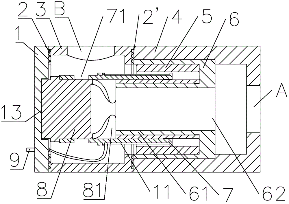
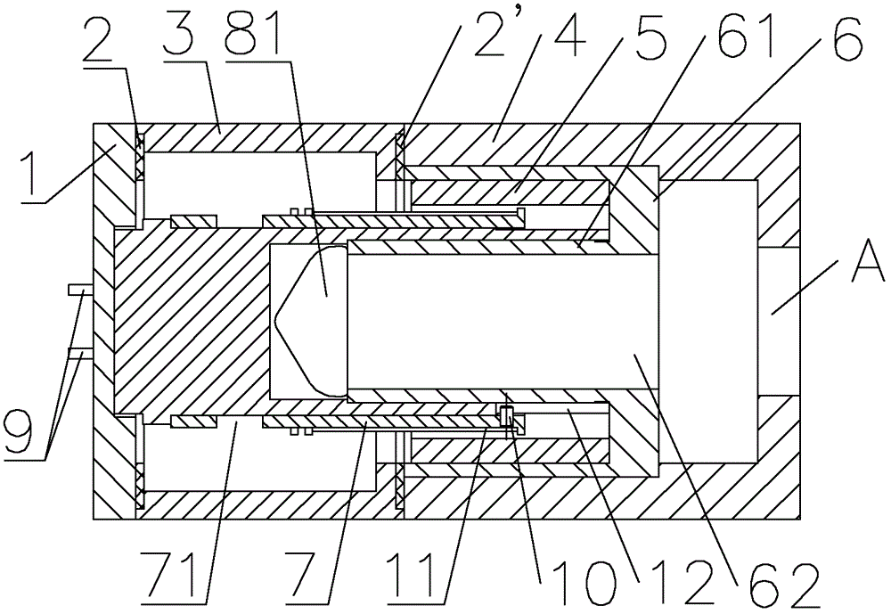
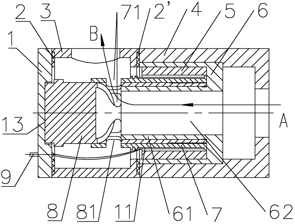
[0029] As the first aspect of the present invention, the present invention provides a flow proportional valve. Such as Figure 1-4 As shown, the flow proportional valve in the present invention includes: a housing with an inlet A and an outlet B; the flow proportional valve also includes a yoke 6, a central shaft sleeve 8, a sliding sleeve 7 and a magnet provided in the housing 5; The yoke 6 includes a guide portion 61, the guide portion 61 has a fluid passage 62, the first end of the fluid passage 62 is in communication with the inlet A; the central sleeve 8 includes an axial hole through which the central sleeve 8 is fixedly ground It is sleeved on the guide portion 61, the central shaft sleeve 8 is provided with a first opening 81 communicat...


PUM


Abstract

The invention provides a breathing machine, an anaesthesia machine and a flow proportional valve. The flow proportional valve comprises a shell body, wherein an inlet and an outlet are formed in the shell body. The flow proportional valve further comprises a magnet yoke, a central shaft sleeve, a sliding shaft, and a magnet which are installed inside the shell body. The magnet yoke comprises a guide portion. The guide portion comprises a fluid channel, wherein a first end of the fluid channel is communicated with the inlet. The central shaft sleeve comprises an axial hole, the central shaft sleeve is fixedly sleeved on the guide portion through the axial hole, a first opening which is communicated with the axial hole is formed in the peripheral wall of the central shaft sleeve, and the first opening is communicated with the outlet. A coil is arranged on the sliding sleeve, the sliding sleeve can be sleeved on the central shaft sleeve in a sliding mode, and the sliding sleeve is provided with a communicating position which enables the first opening and the outlet to be communicated. By applying certain pulsed voltage on the coil, control of the opening degree of the first opening in the central shaft sleeve by the sliding sleeve is realized, and the purpose of high flow proportional control under the low-pressure state is achieved. In addition, the flow proportional valve has the advantages of being simple in structure, fast in responding speed, high in repeated accuracy, and long in service life.

Description

Technical field [0001] The present invention relates to the field of proportional valves, and more specifically, to a ventilator, anesthesia machine and a flow proportional valve. Background technique [0002] The flow proportional valve in the prior art usually uses a voice coil motor to control a certain actuator (such as a cone, a membrane or a baffle) to compress an elastic element to make a linear displacement. This displacement changes the throttle area of ​​the fluid passage, thereby Control the flow of gas. [0003] However, the opening area (that is, the diameter) of the flow proportional valve in the prior art is relatively small. Therefore, in order to achieve a larger flow requirement, a higher input gas pressure is usually used. However, in some airway systems of ventilator or anesthesia machine driven by microturbine, the gas pressure is not high (for example, the pressure generated by the microturbine during normal operation is generally only a few thousand Pascals)...

Claims


Application Information

Patent Timeline
Patent Type & Authority Applications(China)
IPC IPC(8): A61M16/20A61M16/01A61M16/00
Inventor 申佑方
Owner BEIJING AEONMED
Why Eureka
Try Eureka