Compartment stepping washing self-deashing bag-type dust remover and dust removing method
A bag-type dust collector and self-cleaning technology, which is applied in separation methods, chemical instruments and methods, and separation of dispersed particles, can solve the problems of high energy consumption for cleaning dust and affect the service life of filter bags, and achieve air volume and pressure loss. Maintain stability, avoid the increase of air volume, and the effect of simple structure
- Summary
- Abstract
- Description
- Claims
- Application Information
AI Technical Summary
Problems solved by technology
Method used
Image
Examples
Embodiment 1
[0022] This embodiment is applied to the dust purification of the taphole flue gas of the ironmaking blast furnace, and the air inlet pipe of the present invention is connected with the gas collecting hood of the taphole.
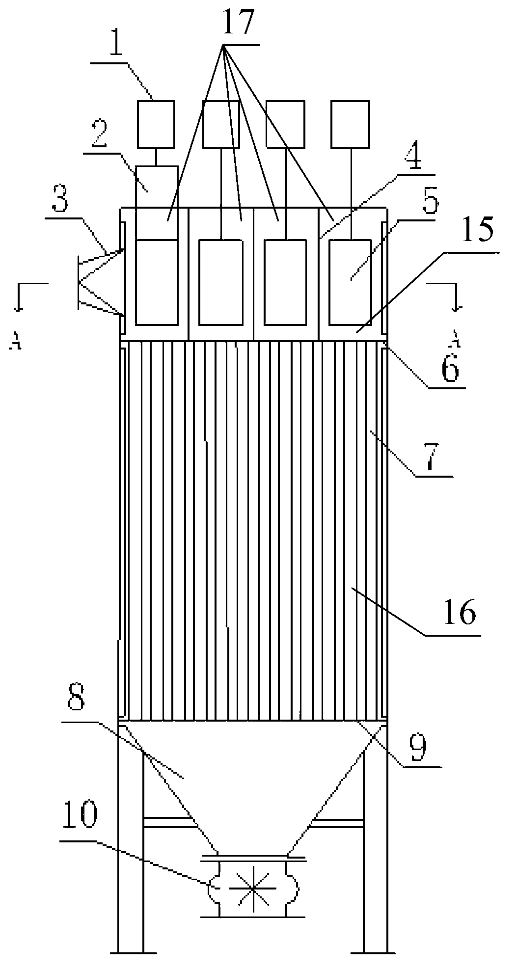
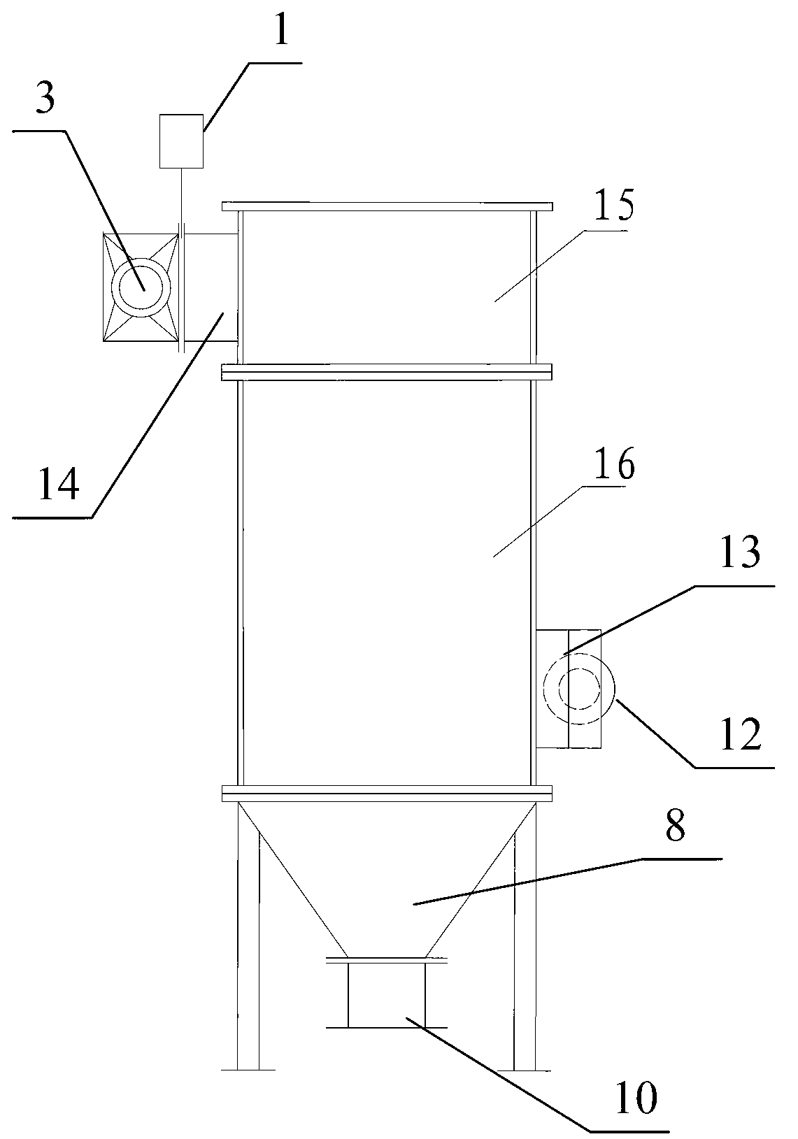
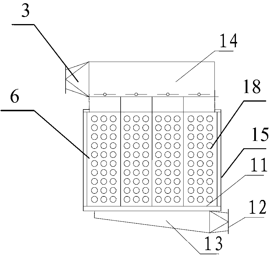
[0023] Such as Figure 1 ~ Figure 3 As shown, a step-by-step scouring self-cleaning bag-type dust collector includes an upper box body 15, and a compartment 17 formed by a compartment partition 4 is arranged inside the upper box body 15. On the side of the upper box body 15 An intake header 14 is provided, and an intake pipe 3 is arranged at one end of the intake header 14; an intake window 5 is arranged between the intake header 14 and each sub-chamber 17, and a gate is arranged on the intake window 5 Plate valve 2, the upper part of the gate valve 2 is connected with the electromagnet 1 outside the sub-chamber 17; a middle box 16 is arranged below the upper box 15, and an upper flower plate 6 is arranged on the top of the middle box 16. The bottom of the...
Embodiment 2
[0037] This embodiment is applied to the purification of flue gas and dust of coal-fired boilers in thermal power plants.
[0038] Such as Figure 1 ~ Figure 3As shown, a step-by-step scouring self-cleaning bag-type dust collector includes an upper box body 15, and a compartment 17 formed by a compartment partition 4 is arranged inside the upper box body 15. On the side of the upper box body 15 An intake header 14 is provided, and an intake pipe 3 is arranged at one end of the intake header 14; an intake window 5 is arranged between the intake header 14 and each sub-chamber 17, and a gate is arranged on the intake window 5 Plate valve 2, the upper part of the gate valve 2 is connected with the electromagnet 1 outside the sub-chamber 17; a middle box 16 is arranged below the upper box 15, and an upper flower plate 6 is arranged on the top of the middle box 16. The bottom of the middle box 16 is provided with a lower flower plate 9, the upper and lower flower plates have throug...
PUM
 Abstract
Description
Claims
Application Information
 - R&D
- Intellectual Property
- Life Sciences
- Materials
- Tech Scout
- Unparalleled Data Quality
- Higher Quality Content
- 60% Fewer Hallucinations
Browse by: Latest US Patents, China's latest patents, Technical Efficacy Thesaurus, Application Domain, Technology Topic, Popular Technical Reports.
© 2025 PatSnap. All rights reserved.Legal|Privacy policy|Modern Slavery Act Transparency Statement|Sitemap|About US| Contact US: help@patsnap.com


