
Manufacture method of break piston

A manufacturing method and technology for pistons, which are applied in the directions of pistons, transportation and packaging, railway car body parts, etc., can solve the problems of complex process, unsmooth operation of the piston rod, reduced production efficiency and work efficiency, etc., so as to simplify the processing technology, improve the The effect of production efficiency and work efficiency

Active Publication Date: 2015-01-14
KOWOO
View PDF6 Cites 0 Cited by
  • Summary
  • Abstract
  • Description
  • Claims
  • Application Information

AI Technical Summary

Problems solved by technology

[0013] The above-mentioned prior art uses a casting process to manufacture brake pistons, and the method of manufacturing brake pistons through a casting process in which molten metal is injected into the mold and then molded, the process is complicated, and the production efficiency and work efficiency are greatly reduced.
[0014] In addition, the conventional brake piston also has the problem that the piston cannot move forward or backward smoothly due to the unsmooth operation of the piston rod for pushing and pulling the piston, which causes the braking force of the brake device to drop significantly.

Method used


Image

  • Manufacture method of break piston
  • Manufacture method of break piston
  • Manufacture method of break piston

Examples


Embodiment Construction

[0053] Hereinafter, the structure and principle of the present invention will be described in detail with reference to the accompanying drawings.

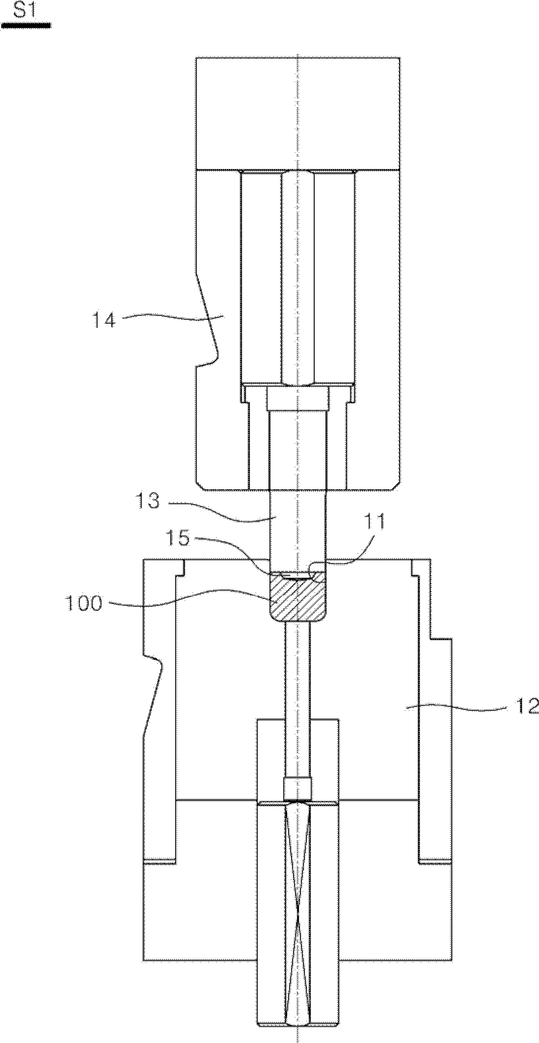
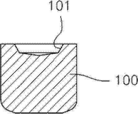
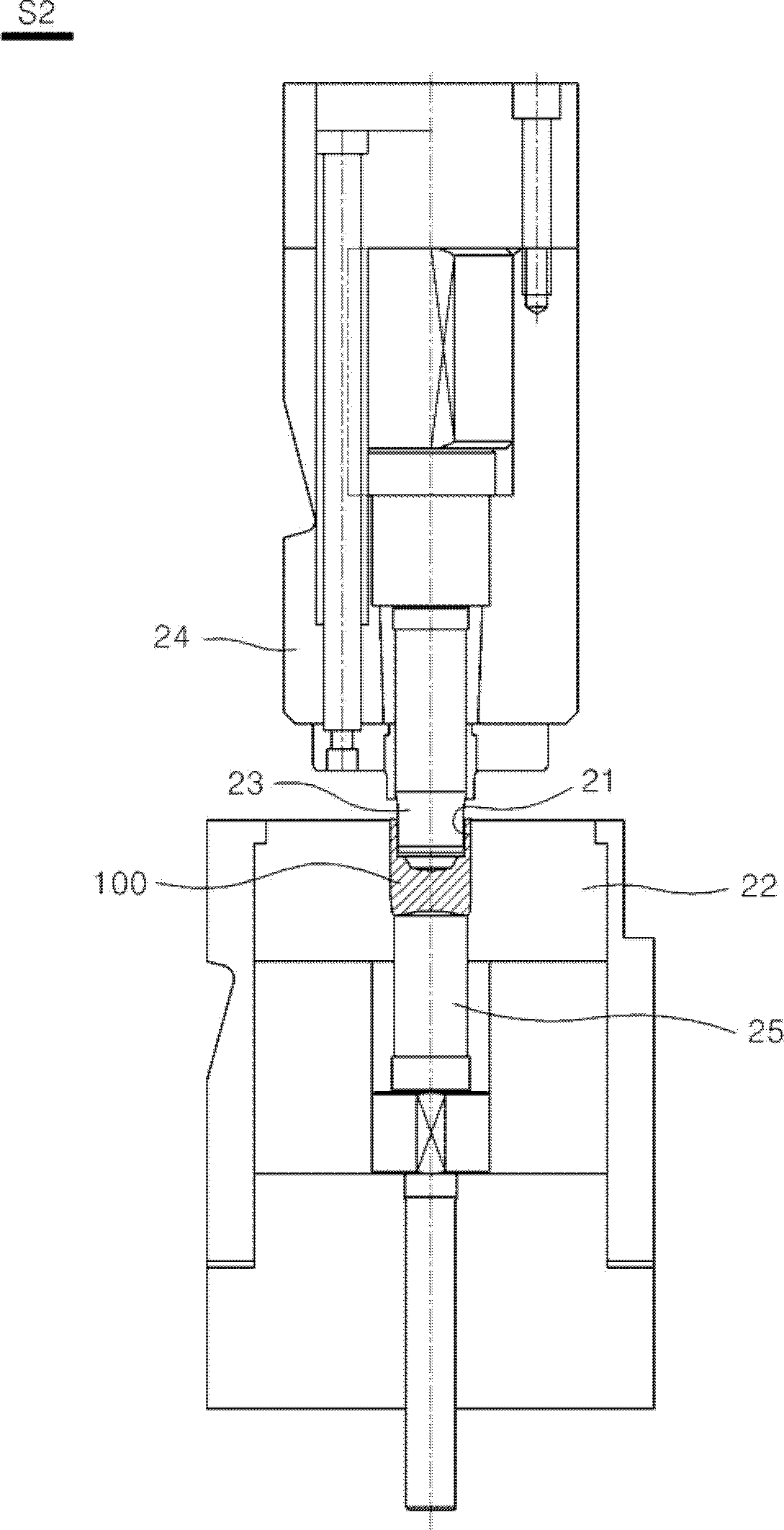
[0054] As shown in the figure, the manufacturing method of the brake piston of the present invention includes: the first process S1 of machining the positioning groove 101 on the casting 100 constituting the piston; the second process S2 of machining the first hollow part 102 on the casting 100; bevel machining on casting 100 The third process S3 of forming the channel groove processing surface 103 ; the fourth process S4 of processing the third hollow portion 104 on the casting 100 ; and the fifth process S5 of processing the second hollow portion 105 on the casting 100 .

[0055] The first process S1 is as figure 1 and figure 2 As shown, the casting 100 is introduced into the first casting introduction part 11 of the first molding die 12 with the first casting introduction part 11 formed on the inner surface of the upper end....


PUM


Abstract

A brake piston manufacturing method is provided to simplify the process of making a piston, thereby improving productivity and work efficiency. CONSTITUTION: A brake piston manufacturing method comprises steps of: putting a material(100) into a first forming dies, pressing a first forming die of a first former cold forming machine to the material to process a position setting groove on the top of the material, putting the material into a second dies, pressing a second forming die of a second former cold forming machine to the material to process a first hollow portion(102) inside the material, putting the material into a third forming dies, pressing a third forming die of a third former cold forming machine to the material to chamfer a flow hole processing surface on the periphery of the first hollow portion of the material, putting the material into a fourth forming dies, pressing a fourth forming die of a fourth former cold forming machine to the material to process a third hollow portion(104) extended from the first hollow portion within the material.

Description

technical field [0001] The invention relates to a method for manufacturing a brake piston, specifically, it relates to a method for manufacturing a brake piston in a cold forming machine The piston casting is placed between the mold and the piston, and when the piston is manufactured by the stamping process of the cold forming machine, the flow path groove is formed inside the piston, which greatly simplifies the manufacturing process of the piston and shortens the time required for the manufacturing process of the piston, thus effectively A method for manufacturing a piston that improves production efficiency and work efficiency. Background technique [0002] Generally speaking, the brake device is divided into the main brake device mainly used in driving and the parking brake device to maintain the parking state of the vehicle. The main brake device is operated by the driver's foot, also called the foot brake. The brake device needs to be manually operated, also known as...

Claims


Application Information

Patent Timeline
Patent Type & Authority Patents(China)
IPC IPC(8): B21D22/02
CPCB21J5/12B21K1/18B21K7/14
Inventor 慎泰重
Owner KOWOO
Learn More