Supercharge Your Innovation With Domain-Expert AI Agents!

Assembly mechanism of welded cam shaft

An assembly mechanism and camshaft technology, applied in welding equipment, resistance welding equipment, resistance electrode holder, etc., can solve the problems of low welding precision, low assembly quality, and low assembly efficiency, and achieve high welding accuracy, fast welding speed, The effect of improving assembly efficiency

Active Publication Date: 2014-11-26
NINGBO SHENGLONG AUTOMOTIVE POWERTRAIN SYSTEM CO LTD
View PDF6 Cites 0 Cited by
  • Summary
  • Abstract
  • Description
  • Claims
  • Application Information

AI Technical Summary

Problems solved by technology

The assembly mechanism of the welded camshaft with the above structure has the following defects in the actual use process: due to manual welding, the welding accuracy is low, so it will not only lead to low assembly quality, but also low assembly efficiency

Method used


Image

  • Assembly mechanism of welded cam shaft
  • Assembly mechanism of welded cam shaft
  • Assembly mechanism of welded cam shaft

Examples


Embodiment Construction

[0025] The present invention will be further described below in conjunction with the accompanying drawings and specific embodiments.

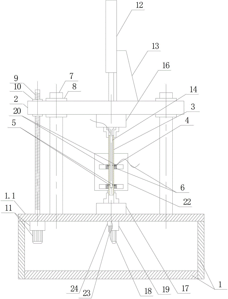
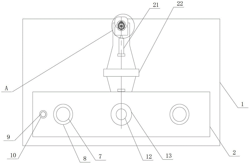
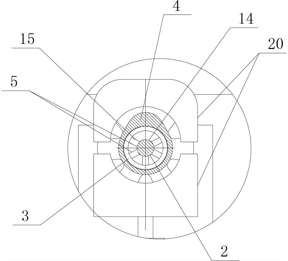
[0026] The welded camshaft consists of a steel pipe 3 and a plurality of cam pieces 4 with different orientations arranged on the steel pipe 3 .

[0027] Such as figure 1 , figure 2 , image 3 , Figure 4 As shown, an assembly mechanism of a welded camshaft of the present invention includes a machine bed 1, a movable plate 2, a driving device arranged on the body inside the machine bed 1 and used to drive the movable plate 2 to move up and down, The resistance welding device on the movable plate 2, the steel pipe clamping device for fixing the steel pipe 3 and the cam piece clamping device arranged on the machine bed 1 and used for clamping the cam piece 4; wherein the machine bed 1 has electrical Components; the steel pipe 3 is limited circumferentially and radially by the steel pipe clamping device.

[0028] The movable plate 2 slides u...


PUM


Abstract

The invention discloses an assembly mechanism of a welded cam shaft. The assembly structure comprises a machine tool body (1), a movable plate (2), a driving device (3), a resistance welding device, a steel tube clamping device and a cam piece clamping device, wherein the movable plate (2) is in vertically sliding fit right above the machine tool body (1), the power output end of the driving device is installed on the movable plate (2), an electrode of the resistance welding device is in vertically sliding fit in a steel tube (3), the cam piece clamping device is provided with another electrode (6), and the central axis of the steel tube (3) fixed by the steel tube clamping device and the central axis of a clamping cam piece (4) clamped by the cam piece clamping device are in the same line. The assembly mechanism is high in assembly quality and efficiency.

Description

technical field [0001] The invention relates to an assembly device for a welded camshaft, in particular to an assembly mechanism for a welded camshaft. Background technique [0002] The welded camshaft consists of a steel pipe and a plurality of cam pieces with different orientations arranged on the steel pipe. [0003] The assembling mechanism of the welded camshaft in the prior art includes a clamp and a welding device. During welding, the camshaft and the cam plate are first clamped by the fixture, and then welded by the operator holding the welding device. The assembly mechanism of the welded camshaft with the above structure has the following defects in the actual use process: due to the manual welding, the welding precision is low, which not only leads to low assembly quality, but also low assembly efficiency. Contents of the invention [0004] The technical problem to be solved by the present invention is to overcome the above defects of the prior art and provide ...

Claims


Application Information

Patent Timeline
Patent Type & Authority Patents(China)
IPC IPC(8): B23K11/00B23K11/31B23K11/30B23K11/36
Inventor 邹娟管慧军许培元罗玉龙
Owner NINGBO SHENGLONG AUTOMOTIVE POWERTRAIN SYSTEM CO LTD
Features
  • R&D
  • Intellectual Property
  • Life Sciences
  • Materials
  • Tech Scout
  • Unparalleled Data Quality
  • Higher Quality Content
  • 60% Fewer Hallucinations
Learn More