
Coated pipe peeling machine

A technology of coating tube and peeling machine, which is applied in metal processing and other directions, can solve the problems of product consistency and low production efficiency.

Active Publication Date: 2015-03-04
HEBEI CHINAUST AUTOMOTIVE PLASTICS CORP LTD
View PDF8 Cites 0 Cited by
  • Summary
  • Abstract
  • Description
  • Claims
  • Application Information

AI Technical Summary

Problems solved by technology

[0007] The purpose of the present invention is to propose a cladding tube peeling machine, which solves the technical problems of product consistency and low product production efficiency in the prior art

Method used


Image

  • Coated pipe peeling machine
  • Coated pipe peeling machine
  • Coated pipe peeling machine

Examples


Embodiment Construction

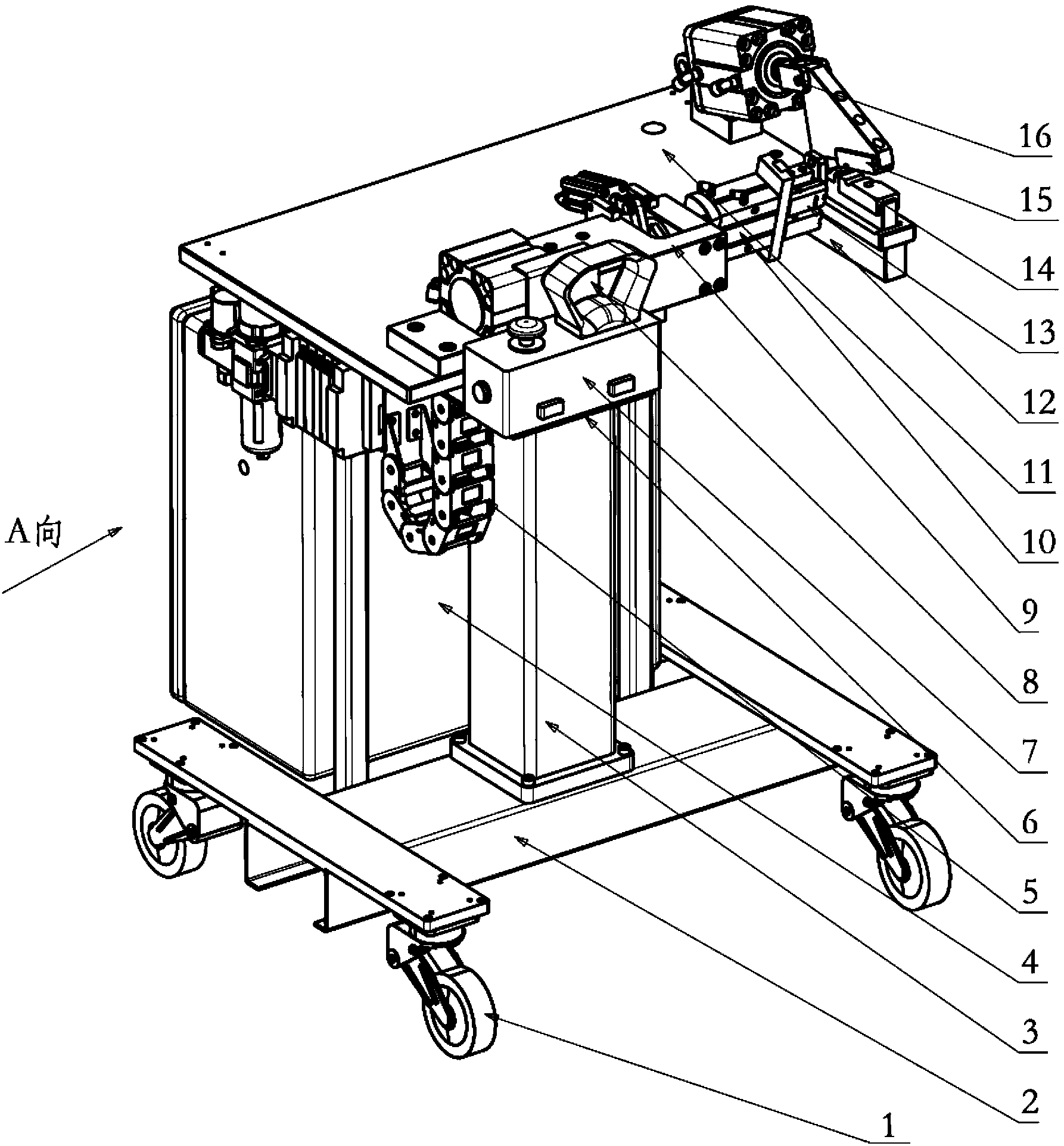
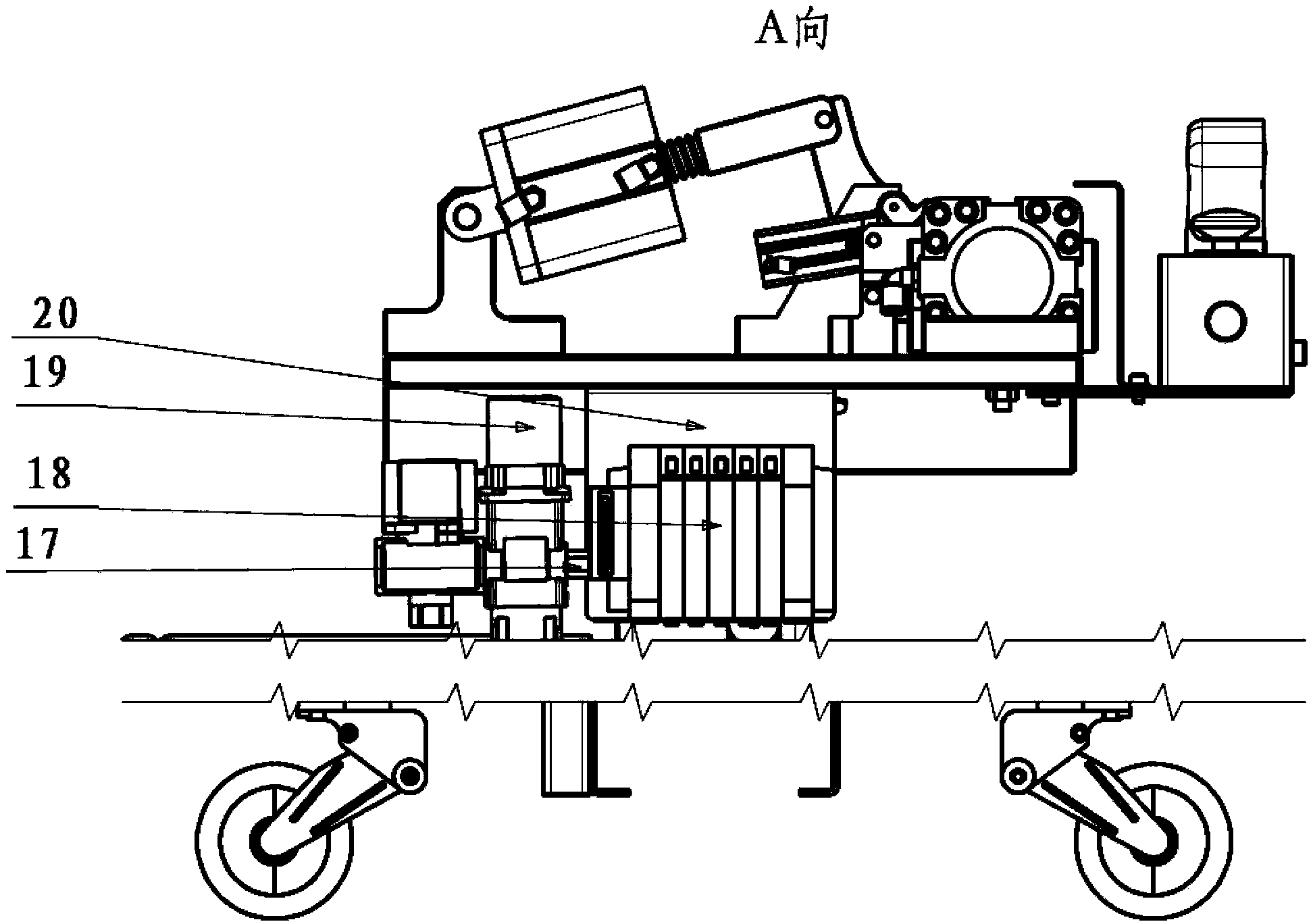
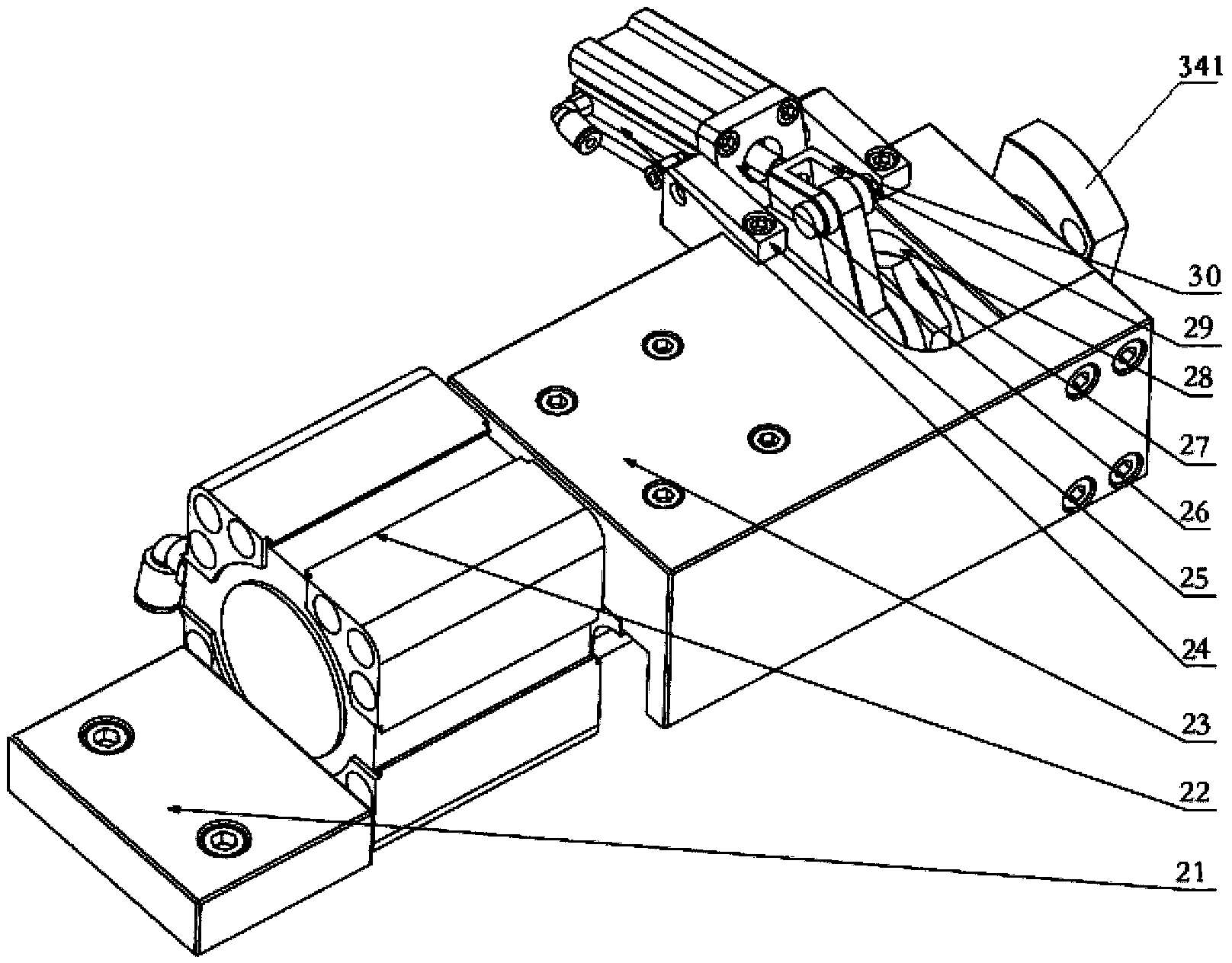
[0078] Below through the accompanying drawings Figure 1 to Figure 12 As well as listing some optional embodiments of the present invention, the technical solutions (including preferred technical solutions) of the present invention are further described in detail. It should be noted that: any technical feature in this embodiment (the technical features can be separated by any punctuation marks such as commas, periods, commas or semicolons), and any technical solution is a variety of optional technical features or One or several of the optional technical solutions, for the sake of brevity in description, it is impossible to list all the alternative technical features and alternative technical solutions of the present invention in this document, and it is not convenient for the implementation of each technical feature It is emphasized that it is one of multiple optional implementation modes, so those skilled in the art should know: any technical feature and any technical scheme ...


PUM


Abstract

The invention discloses a peeling device and a coated pipe peeling machine, and relates to the technical field of automobiles. Technical problems of poor consistency and low production efficiency of products in the prior art are solved. The peeling device comprises a cutting mechanism, a connecting seat and a peeling mechanism; the cutting mechanism is arranged on the connecting seat and comprises a cutter and a cutter driving mechanism, and the cutter driving mechanism can drive the cutter to at least cut a required-to-be-peeled skin coated on the peripheral surface of a pipe or a rod along the radial direction of the pipe or the rod; and the peeling mechanism is connected with the connecting seat and can drive the cutting mechanism via the connecting seat, so that the cutting mechanism can reciprocate along the axial direction of the pipe or the rod. The coated pipe peeling machine comprises the peeling device, the pipe is a coated pipe, and a chuck driving mechanism can drive a chuck to clamp or release the coated pipe. The peeling device and the coated pipe peeling machine are used for improving the consistency and the production efficiency of products.

Description

technical field [0001] The invention relates to the technical field of automobiles, in particular to a coating tube peeling machine. Background technique [0002] The cladding tube is an important part of the car, which includes an inner tube and an outer tube, and the outer tube is also called the outer skin. [0003] Since the inner tube and the outer tube of the coated tube will slide relative to each other during the assembly of the joint, the end of the coated tube should be peeled before the joint is assembled, and the axial dimension of the end of the coated tube should be removed. 5mm outer tube. [0004] In the prior art, the outer tube at the end of the clad tube has been removed by hand. In the process of manual removal, it is necessary to manually mark and position the outer tube of the clad tube, and then use pliers to perform the peeling operation. [0005] There are at least the following technical problems in the prior art: [0006] Since the outer tube at...

Claims


Application Information

Patent Timeline
Patent Type & Authority Patents(China)
IPC IPC(8): B26D3/28B26D5/04B26D7/02
Inventor 郭松涛于水丰
Owner HEBEI CHINAUST AUTOMOTIVE PLASTICS CORP LTD
Learn More