Active maglev electromagnetic catapult

A magnetic levitation and catapult technology, which is applied in the direction of launch/drag transmission, can solve the problem of not eliminating the rolling friction resistance between the aircraft wheel and the deck, and achieve the effects of improving positioning accuracy and ejection speed, adjustable damping, and prolonging the service life

Inactive Publication Date: 2013-04-24
SHANGHAI UNIV
View PDF2 Cites 25 Cited by
  • Summary
  • Abstract
  • Description
  • Claims
  • Application Information

AI Technical Summary

Problems solved by technology

[0008] At present, the United States has successfully used electromagnetic catapults to eject aircraft on land, but the electromagnetic catapults currently developed by the United States only replace the pistons of steam catapults with high-power linear ejection motors. The ejection motors have rollers. A reciprocating vehicle runs along the catapult track under the action of electromagnetic force, pulls the aircraft on the deck and accelerates to take-off speed along the ejection stroke, the aircraft is still placed directly on the deck through the wheels, and the gap between the aircraft wheels and the deck is not eliminated. rolling friction resistance

Method used


Image

  • Active maglev electromagnetic catapult
  • Active maglev electromagnetic catapult
  • Active maglev electromagnetic catapult

Examples


Embodiment 1

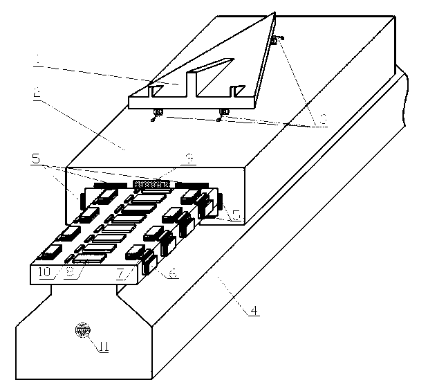
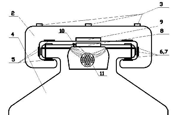
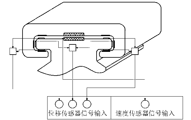
[0028] see figure 1 and figure 2, the active magnetic levitation electromagnetic catapult includes a carrier-based aircraft 1 to be ejected and an ejection platform 2 for placing the carrier-based aircraft and being set on the guide rail, and is characterized in that it also includes a connecting part connected to the carrier-based aircraft 1 on the ejection platform 2 3. An ejection base 4 with a magnetic levitation guide rail, a magnetic material 5 embedded on the ejection platform 2, corresponding to the magnetic material 5 and fixed on the two sides of the magnetic levitation guide rail of the ejection base 4, on the bottom and on the side, and controlled by the control system. And the guide electromagnet 6 and the inductive sensor 7 that is arranged next to the electromagnet 6 to detect the displacement change of the ejection platform, and the linear ejection motor primary winding 8 located on the center line of the top surface of the magnetic levitation guide rail of th...

Embodiment 2

[0030] see figure 1 , the active magnetic levitation electromagnetic catapult includes a carrier aircraft model 1 to be ejected, and an ejection platform 2 for placing the carrier aircraft. The connecting part 3 of the carrier aircraft, which makes the ejection platform firmly connected during ejection and drives the ejection operation of the carrier-based aircraft, and the ejection base 4 with a magnetic levitation guide rail, and the magnetic levitation guide rail on it makes the relative movement between 2 and 4 realize no mechanical Contactless frictionless magnetic levitation technology support, so that the carrier-based aircraft on the ejection platform is only subject to air resistance, the magnetic material 5 embedded on the ejection platform, fixed on the guide rail and controlled by the control system The electromagnet 6 is used to detect the displacement of the ejection platform The variable inductive sensor 7, the primary 8 and secondary 9 of the linear ejection mo...


PUM


Abstract

The invention relates to an active maglev electromagnetic catapult for aircraft carriers. The active maglev electromagnetic catapult comprises a maglev guide rail fixed on a catapult base, a catapult platform sleeved on the guide rail, and a linear motor. The shipboard aircraft catapult platform is supported by active maglev supporting technology and is driven by the high-power linear catapult motor, and catapult-assisted take-off of shipboard aircrafts is achieved. The active maglev supporting technology is introduced, a catapult platform position control system and a speed control system are provided, and accordingly positioning precision and catapulting speed of the catapult platform are increased greatly, electrification is achieved and the service life is prolonged. The active maglev electromagnetic catapult has the advantages of adjustable supporting rigidity and damping, no friction, no need of lubrication, no environment pollution and the like.

Description

technical field [0001] The invention relates to an electromagnetic catapult used on an aircraft carrier, in particular to an active magnetic levitation electromagnetic catapult. Background technique [0002] As the overlord of the sea, the aircraft carrier occupies a central position in naval weapons. The catapult, one of the key components of an aircraft carrier, has always been a major difficulty in aircraft carrier technology. With the rapid growth of our country's economy and the continuous improvement of the level of science and technology, our country already has certain economic strength and technical capabilities to develop its own aircraft carrier. The Liaoning ship aircraft carrier converted from the Varyag is the real starting point of China's aircraft carrier, but it is refitted from an unfinished aircraft carrier bought by our country from Ukraine. There are no key components including catapults at all, only relatively backward slides Leap to help take off the...

Claims


Application Information

Patent Timeline
Patent Type & Authority Applications(China)
IPC IPC(8): B64F1/06
Inventor 张钢张海龙张坚李明彦孙昌孟庆涛支汉立姜笑颖
Owner SHANGHAI UNIV
Why Eureka
Try Eureka