Warp stopping frame

A warp stopper and warp creel technology, applied in the field of warp stoppers, can solve the problems of increasing the extra work intensity of workers, wrong stoppage of looms, and malfunctions, etc., and achieve the effects of shortening downtime of looms, improving weaving efficiency, and avoiding operational errors

Active Publication Date: 2014-01-15
CHANGSHU CHANG XIN TEXTILE EQUIP
View PDF7 Cites 18 Cited by
  • Summary
  • Abstract
  • Description
  • Claims
  • Application Information

AI Technical Summary

Problems solved by technology

[0005] Utility Model Patent Authorization Announcement No. CN2082274U introduces "Electronic Warp Stopper for Looms". Work quickly to find the location of warp breakage
So even after the warp is broken, the chip of the warp strip 2 is connected to the iron-clad by the warp drop piece, and the warp breakage signal cannot be fed back to the electrical control device of the loom by the warp drop junction box 1, that is, the electrical control box. Works as usual, yet fabric is woven with flaws
The current processing method is: workers regularly or irregularly clean the menopause strip junction box 1 to ensure the electrical contact between the menopause strip 2 and the conduction electrode 131. Although this method can work, there are the following technical problems: One, it increases the extra work intensity of the workers; Two, once it is neglected to clean in time, it will still return to its old ways, that is, warp yarn breakage will not stop; Three, there is a risk of malfunction, because when fibers and / or other dust After entering between the menopause strip 2 and the conduction electrode 131, it will appear as a non-contact phenomenon, causing the electrical control device of the loom to generate an incorrect signal, and the loom stops by mistake
Based on this, it can be said that relying on manual cleaning is only a negative measure, because this measure can only have a temporary effect on the surface and cannot reflect the effect of a permanent cure.

Method used


Image

  • Warp stopping frame
  • Warp stopping frame
  • Warp stopping frame

Examples


Embodiment Construction

[0023] In order to enable the examiners of the patent office, especially the public, to understand the technical essence and beneficial effects of the present invention more clearly, the applicant will describe in detail the following in the form of examples, but none of the descriptions of the examples is an explanation of the solutions of the present invention. Any equivalent transformation made according to the concept of the present invention which is merely formal but not substantive shall be regarded as the scope of the technical solution of the present invention.

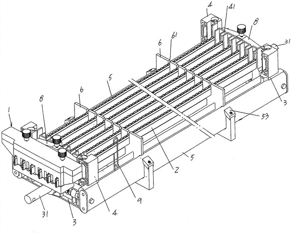
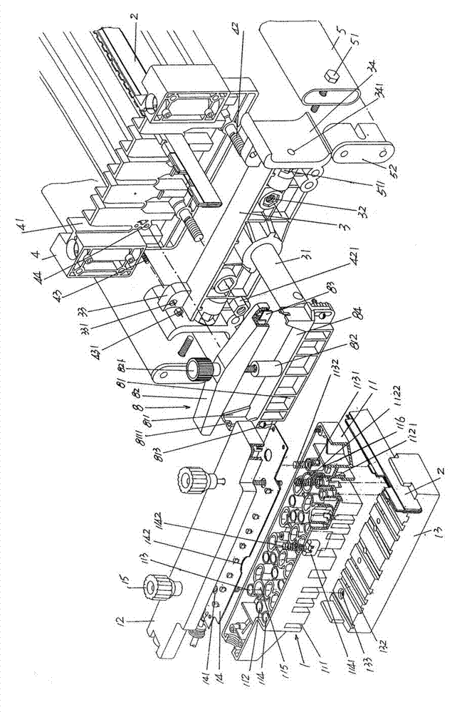
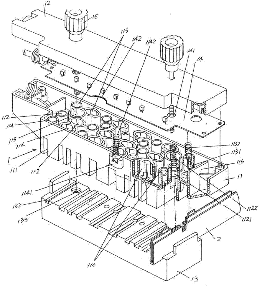
[0024] See Figure 1 to Figure 3 ,Depend on figure 1 As shown, a pair of menopause strip support plates 4 are arranged in a face-to-face manner with each other. Similarly, a pair of menopause strip support plate fixing seats 3 are arranged face to face. A fixed semi-axis 31 is respectively fixed at the central position, and the fixed semi-axis 31 is used for fixed connection with the shuttleless loom. ...


PUM


Abstract

The invention relates to a warp stopping frame and belongs to a shuttleless loom accessory. The warp stopping frame comprises a warp stopping bar junction box, a group of warp stopping bars, a pair of warp stopping bar supporting plate fixing seats, a pair of warp stopping bar supporting plates, a pair of warp frames and a group of warp stopping bar middle supporting plates; the warp stopping bar junction box comprises a box body, a box cover, a box seat and a circuit board, and the group of warp stopping bars comprises an iron clad, a broken warp display protection mechanism and an insulation coating pieces. The warp stopping frame is characterized in that power supply negative pole contact matching notches are opened at the positions on the insulation coating pieces, the positions on the insulation coating pieces correspond to positions between a power supply positive pole contact plate and a signal output contact plate, an upper edge of the iron clad, which corresponds to the positions of the power supply negative pole contact matching notches, is higher than an upper edge of a thin insulation sheet, one end of a power supply negative pole contact is electrically contacted with the iron clad at the position of the power supply negative pole contact matching notches, the other end of the power supply negative pole contact is electrically contacted with one end of a power supply negative pole electric conduction spring, and the other end of the power supply negative pole electric conduction spring is electrically connected with a contact point of a power supply negative pole on the circuit board. By means of the warp stopping frame, reliability of the warp stopping bar junction box responding to warp breaking signals is guaranteed, machine halt time is shortened, and weaving efficiencies are improved.

Description

technical field [0001] The invention belongs to the technical field of accessories of shuttleless looms, and in particular relates to a warp stop frame installed on a shuttleless loom for setting warp stop strips. Background technique [0002] As mentioned above, the function of the menacea frame is to set the warp strips, and the function of the warp strips is to wear the warp sheets, and each warp sheet passes through a warp yarn, and the warp yarns make the warp sheets in a suspended state on the warp strips, so that the warp The chip on the bar and the cladding iron are in a non-conductive state (the chip and the cladding iron are usually insulated and separated by an insulating cladding sheet). During the weaving process of the loom, when the yarn passing through a certain warp dropper breaks, that is, when the yarn breaks, then because the yarn loses the control of the warp dropper, the warp dropper, which was originally in a suspended state, falls to the warp dropper....

Claims


Application Information

Patent Timeline
Patent Type & Authority Patents(China)
IPC IPC(8): D03D51/30
Inventor 陈玉升
Owner CHANGSHU CHANG XIN TEXTILE EQUIP
Why Eureka
Try Eureka