Method and device for automatically checking fastening states of railway fasteners and spring fasteners

A railway fastener and automatic inspection technology, which is applied in the field of instrument science, can solve the problems of collecting image interference system power consumption, reducing the efficiency and accuracy of track inspection, and low sampling rate.

Active Publication Date: 2015-01-21
WUHAN HANNING TECH
View PDF9 Cites 0 Cited by
  • Summary
  • Abstract
  • Description
  • Claims
  • Application Information

AI Technical Summary

Problems solved by technology

The disadvantages of this detection method are:
[0005] 1) The labor intensity is high; the location of the fasteners is low, and the manual has to bend over and lean over, which consumes a lot of physical strength; each fastener is inspected with a manual feeler gauge, the inspectors are prone to fatigue, and the accuracy of the inspection data is difficult to guarantee;
[0006] 2) The detection task is heavy; according to the railway rules, 50 random inspections are performed per kilometer. Taking the 1087 kilometers of Wuhan-Guangzhou high-speed railway as an example, the number of random inspections per year is 1087×2×50=108700. Calculated according to 100 inspections / person / hour, it takes 1087 persons per hour;
[0007] 3) Spot checks cannot guarantee safety; the sampling rate of 50 continuous spot checks per kilometer is low. According to construction standards, there are 1,667 sleepers per kilometer, and each sleeper has 4 sets of track fasteners, a total of 6,668 fasteners, and the sampling rate of spot checks is 50. / 6668=0.75%, does not represent the status of the entire rail fastener
[0008] Therefore, in order to improve the sampling rate, efficiency and accuracy of fastener inspection, the traditional manual inspection method must not be able to complete the task
[0009] Especially the line inspection and maintenance of high-speed railways and urban subways can only be carried out at night, visual fatigue, high rate of missed detection and false detection, harsh working environment, and limited time for track inspection and maintenance
Therefore, the existing manual detection methods cannot quickly and accurately complete the detection of the fastening state of the fastener clips
[0010] During the use of the traditional vehicle-mounted track image inspection system, the on-board computer is mainly used to complete the recording and analysis of the track and fastener images, to determine whether the fastener is intact, whether the spring is broken and displaced, etc., but cannot detect the fastener spring Thirdly, during the use of the traditional vehicle-mounted track image inspection system, the positioning of the fastener is mainly through the combination of the odometer and the track circuit transponder data. The positioning accuracy is generally 5-15 meters, and it cannot be located to a specific Finally, the traditional vehicle-mounted track image inspection system needs to use natural light or high-power lighting, so that the collected image is seriously interfered by sunlight or the power consumption of the system is too large, and the reliability of automatic data processing is difficult to guarantee, which greatly reduces the Improve the efficiency and accuracy of track inspection
[0011] Today, with the increasing development of rail transportation, the traditional way of manually checking the fastening state of fastener clips cannot meet the needs of track management, especially for high-speed railways and urban subways. Therefore, there is an urgent need for a fast, efficient and accurate track Fastening state automatic inspection system for fastener clips

Method used


Image

  • Method and device for automatically checking fastening states of railway fasteners and spring fasteners
  • Method and device for automatically checking fastening states of railway fasteners and spring fasteners

Examples


Embodiment Construction

[0053] The specific embodiments of the present invention will be further described below in conjunction with the accompanying drawings and embodiments. The following embodiments are only used to illustrate the technical solutions of the present invention more clearly, and cannot be used to limit the protection scope of the present invention.

[0054] The method for automatically inspecting the fastening state of a railway spring bar fastener of the present invention includes the following steps:

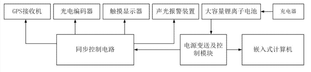
[0055] Step 1: Obtain the positioning data of the railway fastener; the positioning data of the railway fastener includes the absolute position coordinates, linear reference coordinates and sleeper numbers of the railway fasteners, where:

[0056] (1) GPS positioning to obtain the absolute position coordinates of railway fasteners;

[0057] (2) Obtain the linear reference coordinates of the rail car with reference to the starting position of the rail car;

[0058] (3) Count the railway fastene...


PUM


Abstract

The invention relates to a method and a device for automatically checking fastening states of railway fasteners and spring fasteners. The method includes steps of acquiring positioning data of the railway fasteners, acquiring fastening state judgment data of the spring fasteners, combining the positioning data of the railway fasteners and the fastening state judgment data of the spring fasteners to complete checking the fastening states of the railway fasteners and the spring fasteners. The device comprises a railway bogie, a linear structure laser sensor, a photoelectric coder, a GPS (global positioning system) receiver, a synchronous control circuit, an embedded computer and a power source device, wherein the linear structure laser sensor, the photoelectric coder, the GPS receiver, the synchronous control circuit, the embedded computer and the power source device are arranged on the railway bogie. The method and the device for automatically checking the fastening states of the railway fasteners and the spring fasteners have the advantages that accurate positioning of the railway fasteners can be realized, completeness in checking of the railway fasteners and the spring fasteners is realized, the fastening states of the railway fasteners and the spring fasteners can be automatically checked, detail information of the railway fasteners can be recorded, and alarm for the fastening states of the railway fasteners and the spring fasteners is realized.

Description

Technical field [0001] The invention belongs to the field of instrument science and technology, and relates to a method and corresponding equipment for inspecting the fastening state of railway spring bar fasteners, and in particular to a railway spring bar fastener fastening based on multi-sensor integration technology and laser micrometer technology. Method and device for automatic inspection of solid state. Background technique [0002] The track fastener system is a key component of the track structure, which is mainly composed of bolts, nuts, flat washers, spring bars, insulating blocks, iron backing plates, insulating cushion plates, under-rail backing plates, anchor bolts, heavy spring washers, and flat washers And other composition. The failure of fasteners is mainly manifested as missing fasteners, broken spring bars, loose fastening bolts, and elastic failure of spring bars. The basic functions of the track fastener system include: maintaining the gauge, preventing th...

Claims


Application Information

Patent Timeline
Patent Type & Authority Patents(China)
IPC IPC(8): G01B11/00
Inventor 毛庆洲
Owner WUHAN HANNING TECH
Why Eureka
Try Eureka