A kind of multifunctional pull bolt and its application
It is a multi-functional technology for pulling bolts, which is applied to the connection parts of formwork/formwork/work frame, structural elements, building components, etc. It can solve the problems of difficult construction accuracy, many processes, and inconvenient reinforcement operations. Achieve the effects of improving the overall performance of the structure, improving stability and bearing strength, and reducing the time for handover of work types
- Summary
- Abstract
- Description
- Claims
- Application Information
AI Technical Summary
Problems solved by technology
Method used
Image
Examples
Embodiment 1
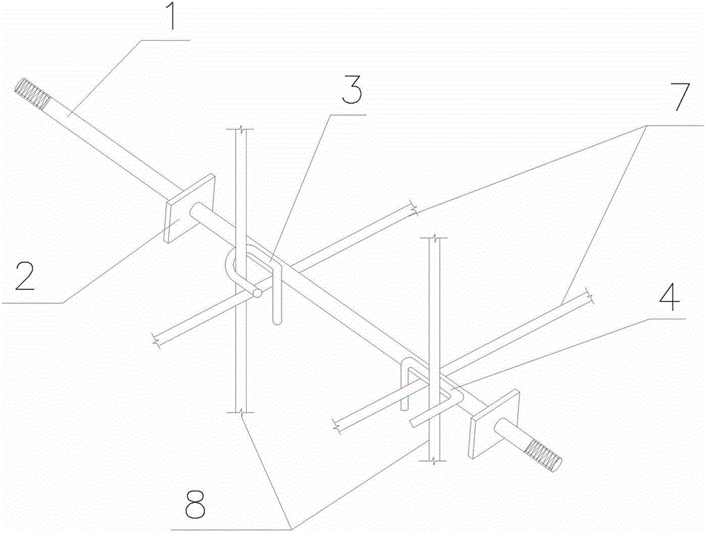
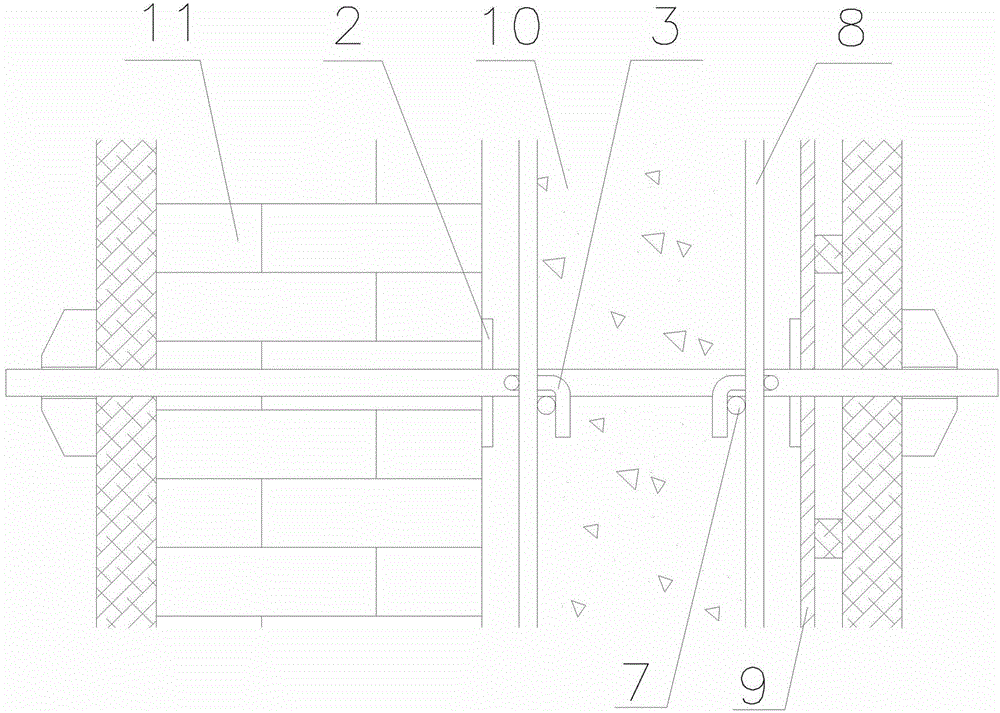
[0046] Embodiment 1: as figure 1 , figure 2 As shown, the two ends of the multi-functional pull bolt 1 used for masonry and concrete composite structure single-side formwork are provided with threads, and the two ends of the bolt rod 1 are respectively equipped with a steel plate, that is, the inner support plate 2 and the outer support plate 5, Both the inner support plate 2 and the outer support plate 5 are square steel plates (or rectangular steel plates), the side length of the inner support plate is 100-200 mm, and the thickness is not less than 6 mm. The side length of 5 is 50-100 mm, and the thickness is not less than 6 mm. The side length of the outer support plate 5 in this embodiment is 80 mm; A pair of positioning cards for binding steel bars are welded on the bolt rod 1 between the outer support plates 5, that is, the inner reinforcing bar positioning card 3 adjacent to the inner supporting plate 2 and the outer reinforcing bar positioning card 4 adjacent to the ...
Embodiment 2
[0067] Embodiment 2: as image 3 As shown, the difference between this embodiment and Embodiment 1 is that a pair of adjusting nuts 6 are assembled on the bolt rod 1 inside the outer support plate 5, and the two adjusting nuts 6 are tightened with each other, and the adjustment nut 6 and the support plate 5 are welded. The outer support plate 5 on one side of the adjusting nut 6 and the bolt rod 1 can be adjusted to form an adjustable outer support plate 51. When the surface of the cast-in-place concrete needs to meet the standard of fair-faced concrete, the adjustable outer support plate of this embodiment can be used. Support plate 51.
[0068] The function of the adjustable outer support plate 51 is the same as that of the non-adjustable outer support plate 5, and the adjustable outer support plate 51 is used for setting up a single-side formwork with high precision requirements. At this time, the length of the screw thread at the end of the pull bolt pull rod 1 should be ...
Embodiment 3
[0073] Embodiment 3: as Figure 5 As shown, this embodiment is used for the process of supporting the formwork on both sides of the inclined plate member, and its operation process is as follows:
[0074] Erection of support frame → Laying of reinforced rib beam and lower formwork 12 → Elastic measurement of steel bar position line and tension bolt location line → Binding of lower reinforcement bar 8 → Laying of tension bolt 1 → Reinforcement and calibration of tension bolt 1 and lower formwork system → Lower reinforcement 8 Positioning → Binding the upper reinforcement 8 and positioning → (use the upper support plate 2 to install and position the embedded parts) → Check for correctness and acceptance → Install the upper formwork 13 → Install the upper formwork 13 to strengthen the rib beam, fasten the pull bolt 1 → Review The lower formwork 12 and its reinforcement → concrete pouring process → after removing the formwork and cutting the exposed bolt ends, the cut ends are tre...
PUM
 Abstract
Description
Claims
Application Information
 - R&D
- Intellectual Property
- Life Sciences
- Materials
- Tech Scout
- Unparalleled Data Quality
- Higher Quality Content
- 60% Fewer Hallucinations
Browse by: Latest US Patents, China's latest patents, Technical Efficacy Thesaurus, Application Domain, Technology Topic, Popular Technical Reports.
© 2025 PatSnap. All rights reserved.Legal|Privacy policy|Modern Slavery Act Transparency Statement|Sitemap|About US| Contact US: help@patsnap.com


