Wear-resistant fan

A technology for fans and wear-resistant plates, applied in mechanical equipment, machines/engines, liquid fuel engines, etc., can solve the problems of reduced blade strength, increased cost, narrow space, etc., to shorten maintenance and replacement time, improve service life, and improve The effect of productivity

Active Publication Date: 2013-04-24
ANHUI ANFENG FAN
View PDF7 Cites 4 Cited by
  • Summary
  • Abstract
  • Description
  • Claims
  • Application Information

AI Technical Summary

Problems solved by technology

[0006]1. The surface of the blade is pasted with ceramics, but the ceramics are greatly affected by the vibration of the fan and the quality of the bonding glue. During use, the ceramics often fall off, and the car must be stopped Repairing, at the same time limited by the bonding glue, the temperature of the currently used medium generally cannot exceed 150 degrees Celsius
[0007]2. Surfacing wear-resistant alloy on the blade body. Surfacing welding will damage the blade body, which will cause the strength of the blade to decrease and reduce its safety. Therefore, only Interval welding can be used, and the wear-resistant layer cannot be surfacing on the entire blade surface. At the same time, it is limited by the thickness of the blade body. The thickness of the grinding is thinner and the gap between the surfacing wear-resistant layer is affected. In actual use, it is often necessary to stop the machine to repair the wear-resistant layer after failure, and repair the welding on the impeller, because the impeller flow path is narrow and the worn part and wear The blades are not the same everywhere, and the uniformity and consistency of manual repair welding are poor, which leads to uneven impact and wear of the dust-laden airflow on the wear-resistant surface of the blades during operation, resulting in damage to the balance of the rotor of the fan, and has to be stopped for maintenance , generally after several repairs, the impeller will be scrapped
[0008]3 Invention patent --- "A wear-resistant boiler induced draft fan impeller application number: 201210172452" and utility model --- "A new wear-resistant fan The impeller, authorized announcement number: 202520616 u "both propose to install wear-resistant materials on the surface of the impeller, but the wear-resistant materials are very difficult to repair and replace after long-term use and failure
[0009]4. The surface of the existing blades is protected by wear-resistant plates, which are fully welded around the wear-resistant plates and the blades, and plug-welded with holes in the middle. After the grinding plate fails, it is necessary to manually blow off the weld seam and replace it with a new wear-resistant plate, but the space in the flow channel of the impeller is narrow, so it is very difficult to repair and replace; and in order to ensure the connection strength between the wear-resistant plate and the blade, the welding must be firm, so The length of the connecting welds is long, and the repeated repairs of the connecting welds that need to be blown off also cause damage to the blades, resulting in a limited number of repairs and replacement of wear-resistant plates, and at the same time, the maintenance intensity is relatively high
[0010] The inlet end of the impeller blade is the most severely worn part of the rotor, so this part is the most prone to wear and failure, so how to improve the wear resistance of this part is also a challenge However, the above-mentioned existing technologies all adopt the method of strengthening the strength of the blade or replacing the blade, without mentioning how to prevent wear and tear, and the method of replacement needs to be shut down, which affects production and increases the cost

Method used


Image

  • Wear-resistant fan
  • Wear-resistant fan
  • Wear-resistant fan

Examples


Embodiment 1

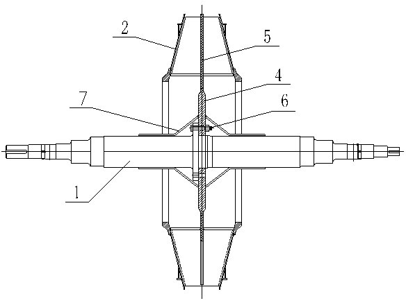
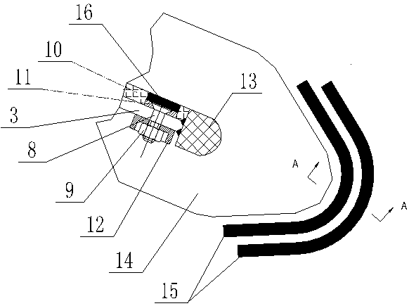
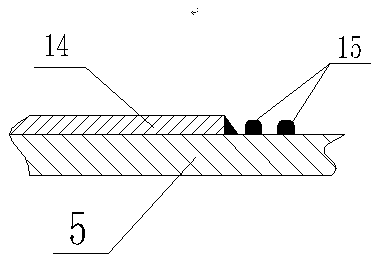
[0028] As shown in the figure, the wear-resistant fan of this embodiment includes a rotor main shaft 1, a wheel cover 2, and blades 3. The blades 3 are welded by an inner middle disk 4 and an outer middle disk 5. The rotor main shaft 1 is connected by connecting bolts. 6 is fixedly connected with the inner disc 4, the key is that the wear-resistant fan also includes a protective cover 7, one end of the protective cover 7 wraps the main shaft 1, and is welded with the main shaft 1, and the other end is welded with the inner disc 4, so that Cover the connecting bolt 6 in the space surrounded by the protective cover 7 , the main shaft 1 and the inner middle disc 4 .

[0029] Protective cover 7 can avoid the washing and wear of dust to connecting bolt 6 and main shaft 1. After protective cover 7 is worn, repair welding or replace it with a new one after all cutting off, because this position is located at the inlet of impeller, which is convenient for replacement and maintenance. ...


PUM


Abstract

The invention aims to provide a wear-resistant fan suitable for delivering high-concentration dust. The wear-resistant fan comprises a rotor spindle, a wheel cap and a blade. The blade is formed by welding an inner central disk and an outer central disk, the rotor spindle is fixedly connected with the inner central disk through a connecting bolt, the wear-resistant fan is characterized by further comprising a protection cover, one end of the protection cover is welded with the spindle, the other end of the protection cover is welded with the inner central disk, and accordingly the connecting bolt covers an inner space enclosed by the protection cover, the spindle and the inner middle disk. An air inlet end of the blade most subjected to wear is protected by utilizing a wear-resistant nose, the blade is protected by utilizing a wear-resistant plate, and the wear-resistant nose and the wear-resistant plate can be replaced limitlessly, and accordingly service life of a rotor of the fan can be greatly prolonged; and time for maintenance and replacement is greatly shortened, loss of a user caused by halt is lowered to the minimum, and accordingly cost is saved, and productivity is increased.

Description

[0001] technical field [0002] The invention belongs to the field of fluid machinery, and in particular relates to a wear-resistant fan. [0003] Background technique [0004] At present, fans are widely used in various industries such as chemical industry, mining, metallurgy, and environmental protection. Due to the limitations of some process requirements and the need to make the medium conveyed by the fan rotor have a high dust concentration, such as a dust concentration greater than 100-200 grams per cubic meter , the rotor wears quickly during use and has a short lifespan. Some have a lifespan of only two to three months. The cost of a larger fan rotor can reach hundreds of thousands. Whether it is frequent maintenance or replacement, it will bring huge losses to users. , so it is an urgent need to develop a long-life fan for transporting high-concentration dust. [0005] The rotor of a traditional fan is composed of the main shaft, the connecting bolts of the main s...

Claims


Application Information

Patent Timeline
Patent Type & Authority Applications(China)
IPC IPC(8): F04D29/00F04D29/30
Inventor 叶团结
Owner ANHUI ANFENG FAN
Why Eureka
Try Eureka