
Delay assembly capable of resisting temperature difference

A combination of components and temperature difference technology, applied in the direction of weapon accessories, fuzes, blasting, etc., can solve the problems of warping and deformation of the cap, unstable delay time, and shortened delay time, etc., to achieve small environmental temperature effects, reasonable structural design, and manufacturing The effect of simple process

Active Publication Date: 2013-04-24
HUNAN SHENFU GRP XIANGHONG MACHINERY CHEM
View PDF6 Cites 2 Cited by
  • Summary
  • Abstract
  • Description
  • Claims
  • Application Information

AI Technical Summary

Problems solved by technology

The main problem of the percussive delayed firing parts currently used in our country is that the ring riveting of the fire cap is not good, which makes the fire cap warped and deformed, which increases the firing energy and reduces the reliability of firing. At the same time, it also leads to unstable delay time and low second difference Large; Affected by harsh environmental conditions such as weather, environment, time, and regional geographical location, the delay time of the ignition part is unstable and the accuracy is poor; affected by the ambient temperature, the delay time of the impact delay ignition part drifts too much, and the combustion temperature effect of the delay element Obviously, the delay time increases when the temperature is low, and the delay time decreases when the temperature is high

Method used


Image

  • Delay assembly capable of resisting temperature difference
  • Delay assembly capable of resisting temperature difference
  • Delay assembly capable of resisting temperature difference

Examples


Embodiment Construction

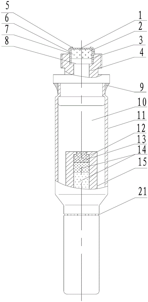
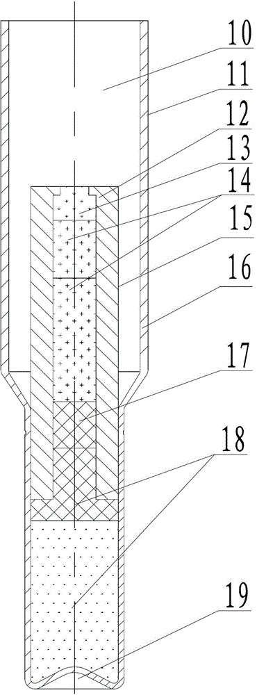
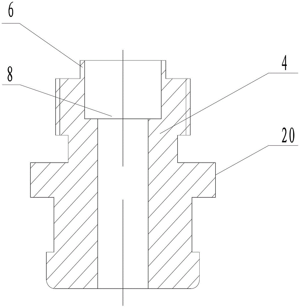
[0018] The present invention will be further described below in conjunction with the accompanying drawings: the ignition element used to ignite the ignition powder 13 is formed by the flash cap shell 1, the percussion charge 2 and the cover sheet 3, and the ignition element hits the flash cap 7, wherein the cover sheet 3 plays a role in fixing the medicament and preventing it from colliding with the flash cap 7 be affected with the effect of being affected with damp; Delay tube case 12, ignition powder 13, delay charge 14, priming charge 17 and explosive 18 form delay time detonation element delay initiation part 15, delay time is mainly controlled by delay charge 14; Detonator shell 16 and Explosives 18 form detonator 19, and delayed detonator 15 and detonator 19 are formed the delayed detonator 11 that delays detonation function. Different medicaments are assembled into impact cap 7, delayed detonator 15 and delayed detonator 11 to form monomers with different functions by us...


PUM


Abstract

The invention discloses a delay assembly capable of resisting temperature difference, which has a completely sealed structure and is composed of a percussion cap 7, a connector 20 and a delay detonator 11, wherein the upper round outer diameter of the shell body of a detonator shell 16 of the delay detonator 11 is large, the bottom round outer diameter of the shell body is small, and the detonator shell 16 is provided with a larger gas storage cavity 10; the connector 20 is provided with a circular convex edge 6 which is used for fixing the percussion cap 7, when shutting and crimping the percussion cap 7, the cap shell tilt can not be caused to bring about medicament looseness, a delay ignition piece 15 in the delay detonator 11 is downward loaded into the bottom small end of the detonator 19 according to the output end, the position of loading small end is in contact with the inner diameter of the small end of the detonator shell 16 and explosive 18, and the rest position is not in contact with any object. According to the invention, the influence of high temperature and high pressure gas generated during medicament burning on burning rate and environment temperature of delay medicine (14) to medicament burning rate is effectively solved and lowered, and the delay accuracy of the delay assembly is improved.

Description

technical field [0001] The invention relates to a delay assembly, in particular to a temperature-difference-resistant delay assembly used in civil blasting, fuzes and ammunition with delayed detonation pyrotechnics. Background technique [0002] With the development of civilian differential blasting technology, the use of pyrotechnic products in urban directional, timing demolition blasting and engineering precision blasting has increased significantly, and the requirements for detonator delay accuracy and environmental use in blasting are also getting higher and higher. The main problem of the percussive delayed firing parts currently used in our country is that the ring riveting of the fire cap is not good, which makes the fire cap warped and deformed, which increases the firing energy and reduces the reliability of firing. At the same time, it also leads to unstable delay time and low second difference Large; Affected by harsh environmental conditions such as weather, env...

Claims


Application Information

Patent Timeline
IPC IPC(8): F42C19/08F42D1/04
Inventor 颜冬林王志朋孙建仪彭渊李贤连易勇禹义勇李灼反
Owner HUNAN SHENFU GRP XIANGHONG MACHINERY CHEM
Features
  • Generate Ideas
  • Intellectual Property
  • Life Sciences
  • Materials
  • Tech Scout
  • Unparalleled Data Quality
  • Higher Quality Content
  • 60% Fewer Hallucinations
Learn More