[0017] The present invention will be described in detail below in conjunction with specific embodiments. The following examples will help those skilled in the art to further understand the present invention, but do not limit the present invention in any form. It should be noted that those skilled in the art can make several modifications and improvements without departing from the concept of the present invention. These all belong to the protection scope of the present invention.
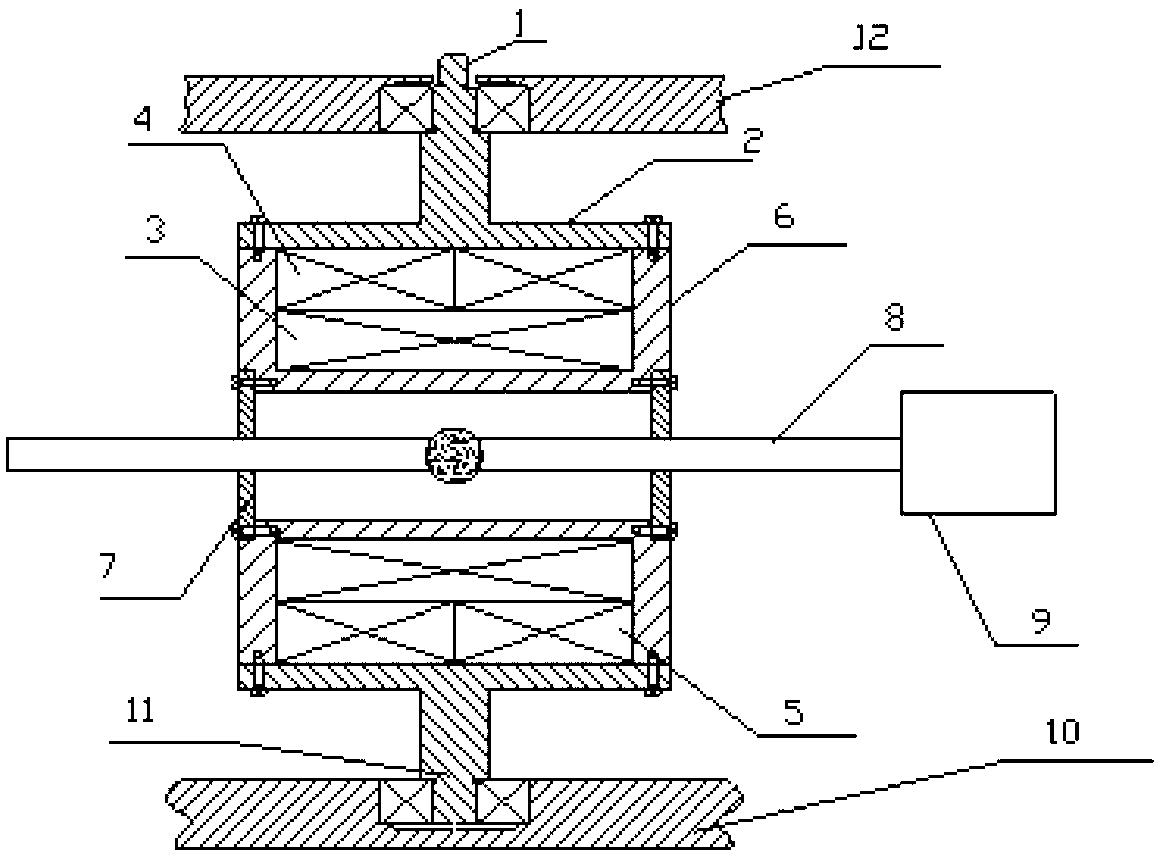
[0018] like figure 1 As shown, in this embodiment, the space mass measuring device provided according to the present invention includes: an upper rotating shaft 1 and a lower rotating shaft 11, a coil housing 2, an excitation and holding coil 3, a first detection coil 4 and a second detection coil Coil 5 , coil support sleeve 6 , sleeve end cap 7 , ferromagnetic droplet module 8 , weighing box 9 , base 10 , and limit cover 12 . The connection relationship is as follows: the upper rotating shaft 1 is located above the lower rotating shaft 11, the upper rotating shaft 1 and the lower rotating shaft 11 are on the same center line, and are respectively connected to the upper and lower sides of the coil casing 2, but do not penetrate the coil. 1 and the extension line of the lower rotating shaft 11 are located at the junction of the first detection coil 4 and the second detection coil 5, that is, bisect the axial distance of the coil housing 2, and are located on the axial centerline of the coil housing 2, and rotate downward The shaft 11 is connected with a bearing, the bearing is installed on the base 10, the limit cover 12 is installed on the upper rotating shaft 1, the upper and lower positions of the limit cover 12 are adjusted to limit the displacement of the whole system along the axial direction of the rotating shaft, the upper The rotating shaft 1 is connected to the motor to generate rotating motion. The coil housing 2 is a sleeve that wraps the entire coil (including the excitation and holding coil 3, the first detecting coil 4, and the second detecting coil 5), and rotates with the upper rotating shaft 1 and the lower rotating shaft. The shaft 11 and the coil support sleeve 6 form an integral body, the excitation and holding coil 3 is wound on the coil support sleeve 6, and the entire coil support sleeve 6 is evenly wound, and the first detection coil 4 and the second detection coil 5 are wound on the Above the excitation and holding coil 3, the relationship is that the first detection coil 4 is wound on the left half of the coil support sleeve 6, and the second detection coil 5 is wound on the right half of the coil support sleeve 6. The first detection coil 4 and the second detection coil 5 are axially symmetrical to the coil support sleeve 6, and a sleeve end cover 7 is respectively installed at the left and right ends of the coil support sleeve 6, and a small hole is respectively opened on the sleeve end cover 7. The hole is located at the axial centerline of the coil support sleeve 6, and is used to place the ferromagnetic liquid droplet module 8. The plastic ball or glass ball of the ferromagnetic droplet module 8 and a part of the long rods at both ends are inside the coil support sleeve 6. , the other part of the long rod at both ends is outside the coil support sleeve 6, and the two ends of the long rod extend out of the sleeve through the small holes at the two ends of the coil support sleeve 6 respectively, and the weighing box 9 is rigidly connected with the right end long rod.
[0019] The coil housing 2 is a sleeve, which is connected with the supporting sleeve 6 by screws to ensure the stability of the whole system.
[0020] The limit cover 12 is installed on the upper rotating shaft 1, and the upper and lower positions of the limit cover 12 are adjusted to limit the displacement of the entire system along the axial direction of the rotating shaft, and can prevent overturning and ensure the operation of the system in a space environment stability.
[0021] The first detection coil 4 and the second detection coil 5 are position sensors, which are located on the left and right sides of the coil support sleeve 6, and are used to detect the position of the ferromagnetic droplet module 8. The calibrated data corresponds to the measure the actual mass of the object.
[0022] The excitation and holding coil 3 is fed with a sinusoidal excitation signal with a DC bias, and the DC bias causes a gradient magnetic field to be generated inside the solenoid, and the magnetic force generated by the magnetic droplet module offsets the centrifugal force on the iron, and at a certain position reaches balance.
[0023] The ferromagnetic droplet module 8 is a long-rod module with a plastic ball or glass ball in the middle and a symmetrical long rod at both ends, wherein the middle plastic ball or glass ball is evenly filled with ferromagnetic liquid.
[0024] The weighing box 9 is a container for holding the measured object, and the weighing box of the corresponding size can be replaced when the size of the object changes.
[0025] The base 10 is the supporting structure of the whole system.
[0026]When the present invention works, the system is placed and installed on the base 10, the lower rotating shaft 11 cooperates with the bearing, and the limit cover 12 is adjusted to ensure that the whole system cannot move along the axial direction of the rotating shaft. The object to be measured is put into the weighing box 9 . When the liquid droplet is at the center of the solenoid, the electromotive force of the excitation signal coupled to the first detection coil 4 and the second detection coil 5 is theoretically zero after being subtracted by the differential connection. The droplet is in a stable equilibrium at the center point. When an external force causes the droplet to deviate from the center position, the magnetic force always tries to make it return to the center. If an external force causes the droplet to deviate from the center position, the first detection coil 4 and the second detection coil 5 will generate a differential electromotive force. When the measurement starts, the upper rotating shaft 1 is driven by the motor to rotate smoothly at a constant speed. Since the objects in circular motion are all subjected to centrifugal force, and since there is an object to be measured at the weighing end of the ferromagnetic droplet module 8, the mass of the weighing end is higher than that of the other end. Large, from the formula centrifugal force=mass of object×square of linear velocity/radius (or mass of object×square of angular velocity×radius), it can be seen that the ferromagnetic droplet module 8 will generate a certain displacement to the weighing end. Due to the effect of the gradient magnetic field that excites and holds the coil 3, at a given uniform speed, the sum of the centrifugal force vector and the magnetic field force received by the ferromagnetic droplet module 8 at a certain position cancels out, reaches equilibrium and stops at that position . The test circuit behind the first detection coil 4, the second detection coil 5, and the excitation and holding coil 3 converts the change of the electromotive force into an electric quantity to detect the position of the ferromagnetic droplet. Through the calibration of the original data, the measured the mass of the object.
[0027] Specific embodiments of the present invention have been described above. It should be understood that the present invention is not limited to the specific embodiments described above, and those skilled in the art may make various changes or modifications within the scope of the claims, which do not affect the essence of the present invention.