Adjustable supporting device for Hopkinson test bar piece

A technology of supporting devices and test rods, which is applied in the direction of measuring devices, instruments, scientific instruments, etc., can solve problems such as the limitation of the diameter of the supporting rod, the inability to adjust the position of the rod, and the complexity of the structure and process, so as to achieve high-precision adjustment and ensure the same The effect of axiality and simple structure

Inactive Publication Date: 2013-04-24
NANJING UNIV OF SCI & TECH
View PDF4 Cites 16 Cited by
  • Summary
  • Abstract
  • Description
  • Claims
  • Application Information

AI Technical Summary

Problems solved by technology

Articles entitled "Mechanical behavior of acrylic under high strain rate tensile loading" (N.K.Naik, Polymer Testing, 27, 504–512, 2008) and "Combined experimental and numerical analysis of bulge test at high strain rates using split Hopkinson pressure bar apparatus” article (Maziar Ramezani, Journal of Materials Processing Technology, 210, 1061–1069, 2010) uses a gate-type device to support the bar. The accuracy of the seat and the support device itself puts forward higher requirements, and the diameter of the support rod is limited
The article titled "Creep, recovery and high strain rate response of soft roll cover materials" (T.Vuoristo, Mechanics of Materials, 34, 493–504, 2002) adopts a more complex support structure, using the level of the structure and vertical movement to adjust the position of the rod. This method has complex structure and process, high processing cost, and also has restrictions on the diameter of the rod.

Method used


Image

  • Adjustable supporting device for Hopkinson test bar piece
  • Adjustable supporting device for Hopkinson test bar piece
  • Adjustable supporting device for Hopkinson test bar piece

Examples


Embodiment Construction

[0011] The support device of the Hopkinson bar is an important part of the Hopkinson test, and it is an important device to ensure the horizontal one-dimensional movement of the bar.

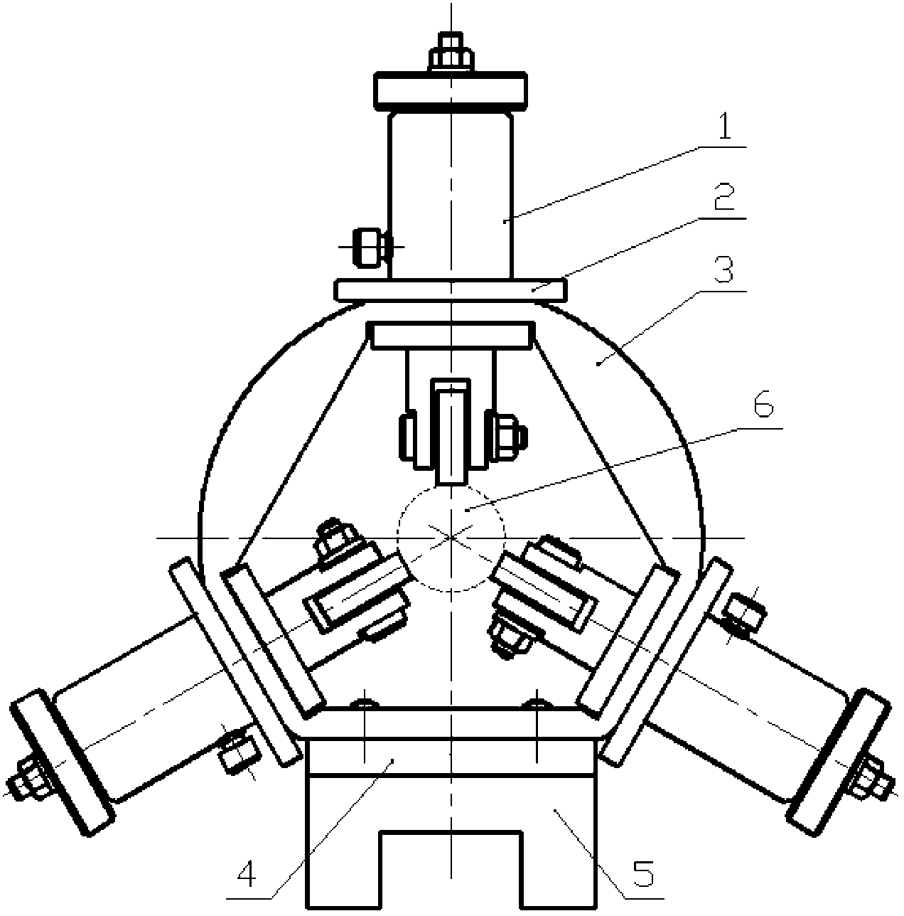
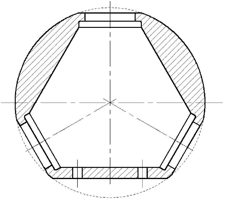
[0012] In conjunction with the accompanying drawings, an adjustable support device for a Hopkinson test rod of the present invention includes an adjustment member 1, a lock nut 2, a bracket 3, an adapter block 4, a slider 5 and a rod 6, and the slider 5 An adapter block 4 is arranged on it, and the adapter block 4 is fixedly connected to the bracket 3, and three adjustment pieces 1 for supporting the rod 6 are uniformly arranged on the bracket 3, and each adjustment piece 1 is fixed on the bracket 3 by a lock nut 2 , the included angle between the central axes of every two adjustment parts 1 is 120 degrees.

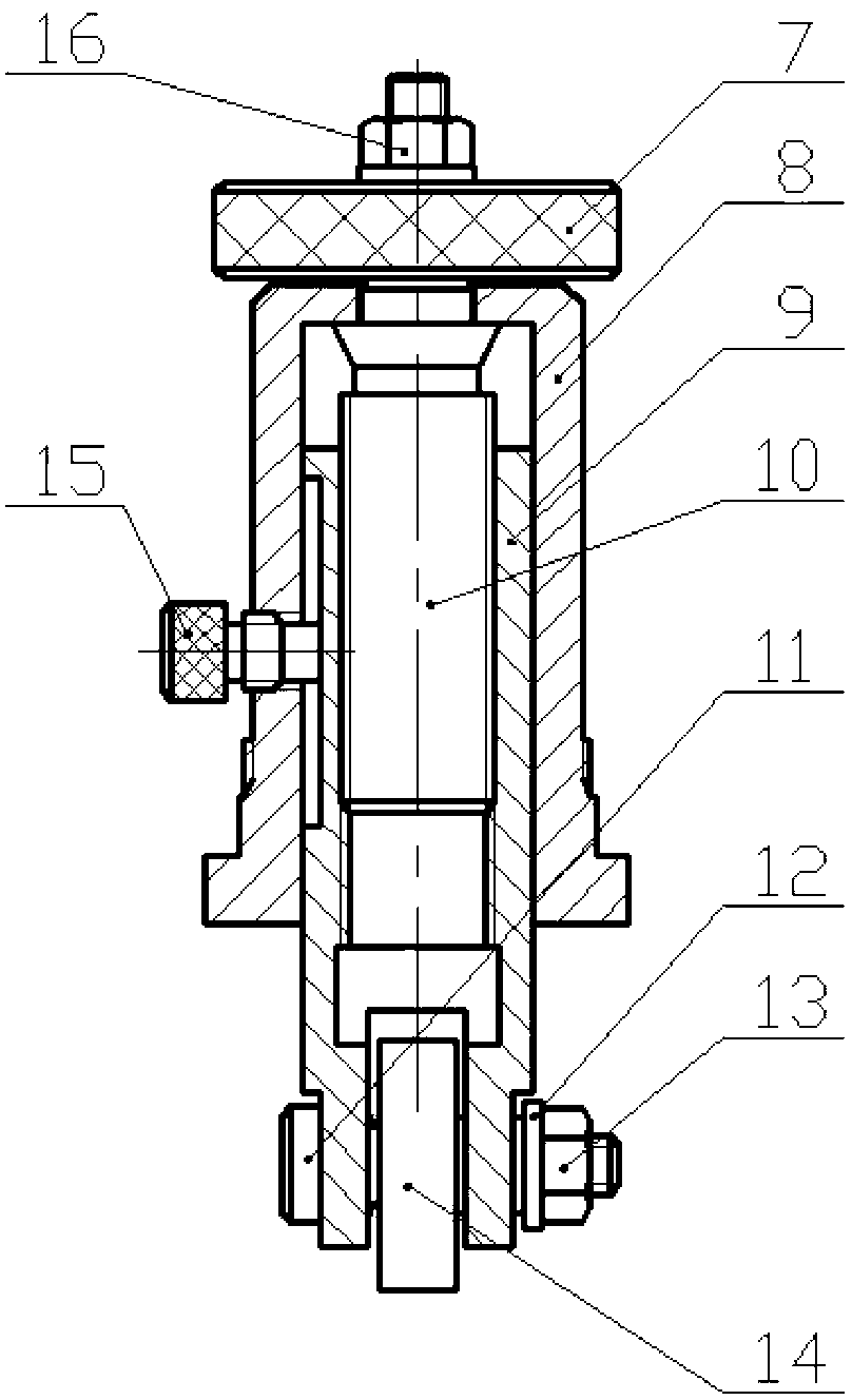
[0013] The adjusting part 1 includes a manual wheel 7, a sleeve 8, a plug shaft 9, an adjusting screw 10, a transverse shaft 11, a collar 12, a lock nut 13, a bearing 14, a brake screw 15 a...


PUM


Abstract

The invention relates to a bar piece supporting device designed according to the Hopkinson test conditions. The bar piece supporting device mainly consists of adjusting parts, locking nuts, a support frame, an adapter block, a slide block and bar pieces, and is mainly and structurally characterized in that the three adjusting parts capable of freely extending and contracting along shaft lines of the adjusting parts are uniformly distributed on an annular framework, the center space size and the position of the supporting device are adjusted, and further, the center bar pieces are supported, and the axial motion of the bar pieces is limited; the bar pieces are supported by bearings at the end parts of the adjusting parts; and meanwhile, the free axial motion of the bar pieces is realized by utilizing the rotation of the bearings. The bar piece supporting device is formed by the simple parts and has the advantages of simplicity, reliability, small size, large adjustable scope, bearing rolling friction adopted in the bar pieces and small resistance, and the degree of freedom of the bar pieces and the rotation motion along shafts can be effectively limited; meanwhile, the axial motion of the bar pieces can not be influenced basically; and as the adjusting scope of the supporting device self is large, the bar piece supporting device can adapt to the bar pieces of which the diameters are within a certain scope.

Description

technical field [0001] The invention belongs to the field of material dynamic mechanics research, in particular to an adjustable support device for a Hopkinson test rod. Background technique [0002] The separate Hopkinson test device is one of the important methods to study the mechanical properties of materials, and its principle is based on the one-dimensional stress wave. Although the principle and technology of the separate Hopkinson test device have been developed and matured, the test device itself has not been standardized and needs to be further developed. According to the one-dimensional stress wave foundation, the horizontality and coaxiality of the Hopkinson rods are highly required in the test, so the adjustment and support of the rods are very important. At the same time, for the test of different materials, there are also different requirements for the diameter of the rod. Articles entitled "Mechanical behavior of acrylic under high strain rate tensile loadi...

Claims


Application Information

Patent Timeline
Patent Type & Authority Applications(China)
IPC IPC(8): G01N3/04
Inventor 张君发鞠玉涛周长省郑健陈雄孙朝翔周清春
Owner NANJING UNIV OF SCI & TECH
Why Eureka
Try Eureka