A receiver circuit of an RFID reader-writer and its implementation method

A receiving end and reader technology, applied in the field of receiving end circuits of RFID readers, can solve problems such as data loss, communication signal demodulation errors, etc., so as to improve the accuracy of data identification and the success rate of reading and writing, and improve the The effect of successful reading and writing rate and data recognition accuracy

Inactive Publication Date: 2015-09-16
FOSHAN KUWEI MICROELECTRONICS
View PDF4 Cites 0 Cited by
  • Summary
  • Abstract
  • Description
  • Claims
  • Application Information

AI Technical Summary

Problems solved by technology

However, in the communication process of non-contact radio frequency identification, the communication signal of 10% modulation depth returned by the passive electronic tag to the reader is easily lost by noise and antenna matching, etc. Performance on the receiving end presents a challenge
Moreover, the quality of the communication signal will decrease as the distance between the reader and the electronic tag increases, resulting in errors in the demodulation of the communication signal. Therefore, a compromise between the quality of the communication signal and the performance of the receiving end is formed in the design. That is to say, in order to realize the established long-distance work, it is necessary to design a good-performance receiver circuit architecture of the reader

Method used


Image

  • A receiver circuit of an RFID reader-writer and its implementation method
  • A receiver circuit of an RFID reader-writer and its implementation method
  • A receiver circuit of an RFID reader-writer and its implementation method

Examples


Embodiment Construction

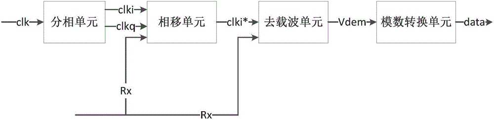
[0038] Depend on figure 1 Shown, a kind of receiving end circuit of RFID reader-writer, comprises:

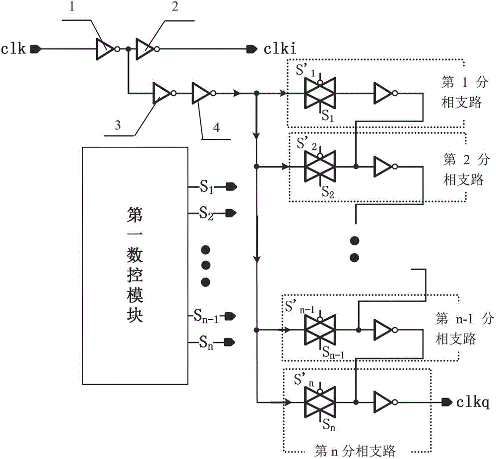
[0039] The phase splitting unit is used to receive the input acquisition clock signal clk, and convert the input acquisition clock signal clk into a first clock signal clki and a second clock signal clkq and then output them to the phase shift unit, the first clock signal Both the frequency of clki and the frequency of the second clock signal clkq are the same as the frequency of the acquisition clock signal clk, and the phase difference between the first clock signal clki and the second clock signal clkq is 83°-98°;

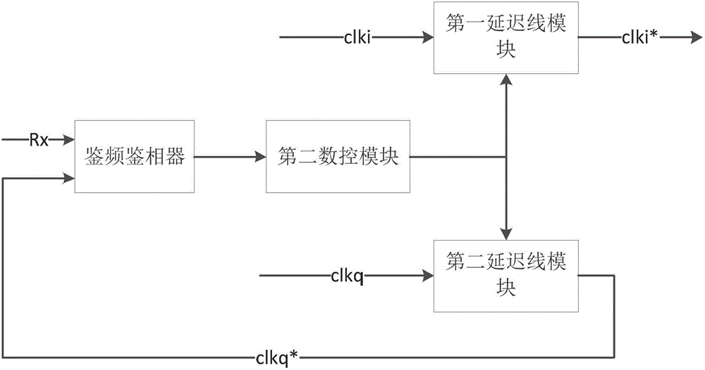
[0040]The phase shifting unit is configured to, after receiving the input radio frequency signal Rx, the first clock signal clki and the second clock signal clkq, further make the first clock signal clki and the second clock signal clkq according to the phase of the input radio frequency signal Rx The phase delay is carried out synchronously, and when the phase ...


PUM


Abstract

The invention discloses a receiving end circuit of a radio frequency identification (RFID) reader-writer and an implementation method of the receiving end circuit of the RFID reader-writer. The receiving end circuit of the RFID reader-writer comprises a split-phase unit, a phase shift unit, a carrier wave removal unit and an analog-digital conversion unit. The implementation method of the receiving end circuit of the RFID reader-writer comprises converting an input acquisition clock signal into a first clock signal and a second clock signal, enabling the first clock signal and the second clock signal to synchronously carry out phase delay according to a phase position of a radio-frequency signal, outputting a third clock signal when phase difference between a fourth clock signal and the radio-frequency signal is from 0 degree to 8 degrees, carrying out sampling on the radio-frequency signal according to the third clock signal, carrying out analog-digital conversion after obtaining carrier wave removal information, and outputting the carrier wave removal information. The receiving end circuit of the RFID reader-writer and the implementation method of the receiving end circuit of the RFID reader-writer are capable of greatly improving data identification accuracy and read-write success rate of the RFID reader-writer, and are capable of supporting telecommuting. The receiving end circuit of the RFID reader-writer and the implementation method of the receiving end circuit of the RFID reader-writer are widely used in the technical field of radio frequency identification.

Description

technical field [0001] The invention relates to electronic circuit technology, in particular to a receiving end circuit of an RFID reader-writer and a realization method thereof. Background technique [0002] Radio frequency identification technology (RFID technology) is actually the specific application and development of automatic identification technology in radio technology. A basic radio frequency identification system includes two parts: a reader and a transponder (also known as an electronic tag). Automatic recognition of various objects or equipment (personnel, items) in different states (moving, stationary or harsh environments). Due to its advantages of non-contact, convenience, and large amount of stored information, radio frequency identification technology is increasingly widely used in many fields such as logistics management, traffic management, access control system, and production automation. [0003] According to the different power supply methods of elec...

Claims


Application Information

Patent Timeline
Patent Type & Authority Patents(China)
IPC IPC(8): G06K17/00
Inventor 段志奎王德明丁一吴劲路崇
Owner FOSHAN KUWEI MICROELECTRONICS
Why Eureka
Try Eureka