Fault protection applied to wind power plant and energy stabilization circuit

A technology for stabilizing circuits and fault protection, which is applied to emergency protection circuit devices, emergency protection circuit devices, circuit devices, etc. for limiting overcurrent/overvoltage, which can solve the problem of increasing the capacity of the converter and failing to provide complete protection. And other issues

Inactive Publication Date: 2013-04-24
INST OF ELECTRICAL ENG CHINESE ACAD OF SCI
View PDF7 Cites 6 Cited by
  • Summary
  • Abstract
  • Description
  • Claims
  • Application Information

AI Technical Summary

Problems solved by technology

The above two methods can play a certain role, but still have the following deficiencies: 1. The current fault protection circuit needs to trigger the corresponding circuit to protect after detecting the fault signal, so it has a certain delay and cannot play a role. The role of complete protection
2. Adopting an improved control method needs to increase the capacity of the converter, and there is nothing that can be done when the voltage drops deeply

Method used


Image

  • Fault protection applied to wind power plant and energy stabilization circuit
  • Fault protection applied to wind power plant and energy stabilization circuit
  • Fault protection applied to wind power plant and energy stabilization circuit

Examples


Embodiment Construction

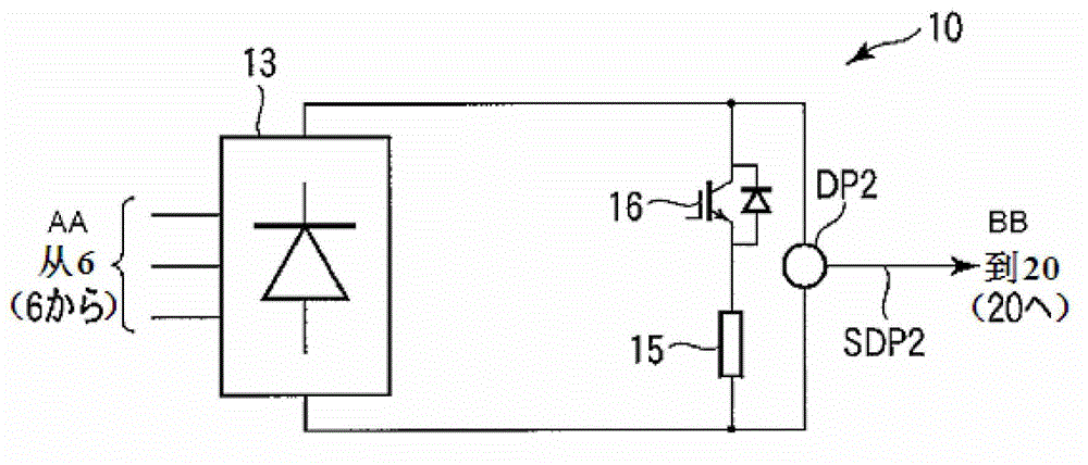
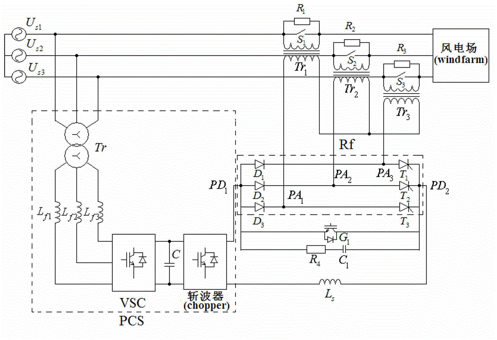
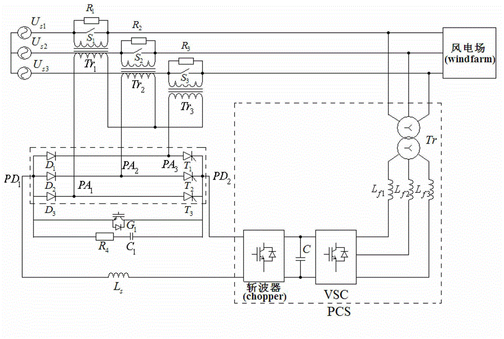
[0017] image 3 It is the topology structure of Embodiment 1 of the present invention. Such as image 3As shown, the structure of Embodiment 1 of the present invention is as follows: the voltage source converter VSC, the three-phase filter circuit, the chopper and the three-phase transformer Tr form a parallel power regulation system PCS; the first diode D1, the second two The pole transistor D2, the third diode D3, the first thyristor T1, the second thyristor T2 and the third thyristor T3 form a three-phase rectifier bridge Rf; the first diode D1, the second diode D2 and the third diode The anodes of the transistor D3 are connected to each other to form the first DC connection point PD1; the cathodes of the first thyristor T1, the second thyristor T2 and the third thyristor T3 are connected to each other to form the second DC connection point PD2; the first diode D1 The cathode is connected to the anode T1 of the first thyristor to form the first AC connection point PA1; th...


PUM


Abstract

Provided is a fault protection applied to a wind power plant and an energy stabilization circuit. A power converter is composed of a voltage source converter and a chopper or a current source converter. A direct current end of a rectifier is connected with a switch provided with an antiparallel diode and a buffer absorption circuit in parallel. A primary side of a single-phase transformer is connected with a switch and a resistor in parallel, and a secondary side of the single-phase transformer is connected with an alternative current output end of the rectifier. The primary side of the single-phase transformer is respectively connected with a power grid and a switching-in end of the wind power plant. A three-phase alternative current end of a power converter is connected with the power grid and a switching-in end of the wind power plant through a three-phase filter circuit and a three-phase transformer. A direct current end of the power converter is connected with a direct current end of the rectifier in series and then connected with an energy storage inductor in series. Under a normal condition, power output of the wind power plant is smoothed through charging and discharging of the energy storage inductor. Under a fault condition, the energy storage inductor is firstly utilized to limit current, then a thyristor of the rectifier is turned off, and the energy storage inductor is disengaged from the power grid. Current is limited through the resistor connected with the primary side of the transformer in parallel.

Description

technical field [0001] The invention relates to a fault protection and energy stabilization circuit for a wind farm. Background technique [0002] Wind power is developing rapidly around the world, and its proportion in the grid is gradually increasing. As the proportion of wind power in the power grid continues to increase, wind power has an increasing impact on grid stability and power quality. In order to reduce the impact of wind power generation on the power grid, countries around the world have gradually introduced grid-connected standards for wind power generation, one of which is to require wind power generators to be disconnected from the power grid only when they meet certain requirements when the voltage is low. In order to meet the requirements of low-voltage grid connection, various low-voltage ride-through technologies have been gradually developed. Various low-voltage ride-through technologies are mainly divided into two types: 1. Using fault protection circ...

Claims


Application Information

Patent Timeline
Patent Type & Authority Applications(China)
IPC IPC(8): H02H9/02H02J3/24
Inventor 郭文勇肖立业戴少涛
Owner INST OF ELECTRICAL ENG CHINESE ACAD OF SCI
Why Eureka
Try Eureka