
Magnetic electricity mixed continuous driving method and motive power device

A hybrid continuous, driving method technology, applied in the direction of electromechanical devices, electric components, electrical components, etc., can solve the problems of high cost, high fuel consumption, environmental pollution, etc., and achieve the effect of reducing friction and improving energy conversion rate

Inactive Publication Date: 2013-04-24
罗琨
View PDF8 Cites 4 Cited by
  • Summary
  • Abstract
  • Description
  • Claims
  • Application Information

AI Technical Summary

Problems solved by technology

[0002] At present, various prime movers such as gasoline engines, diesel engines, and fuel steam engines have been widely used in many fields such as industry, agriculture, transportation, and national defense. Hidden dangers; some of these equipment have huge investment, some consume high fuel costs, and waste emissions, noise, etc. cause serious environmental pollution
Moreover, the energy used by the above-mentioned engines is non-renewable resources such as coal, oil, etc. Due to limited resources, energy consumption has been paid more and more attention by people, and its energy conversion process is complex, costly, low in efficiency, and seriously pollutes the environment.
[0003] At present, there is no power machine on the market that can use electric energy and magnetic properties, or only use less electric energy to continuously output energy, and can achieve the output power of common motors or engines.

Method used


Image

  • Magnetic electricity mixed continuous driving method and motive power device

Examples


Embodiment

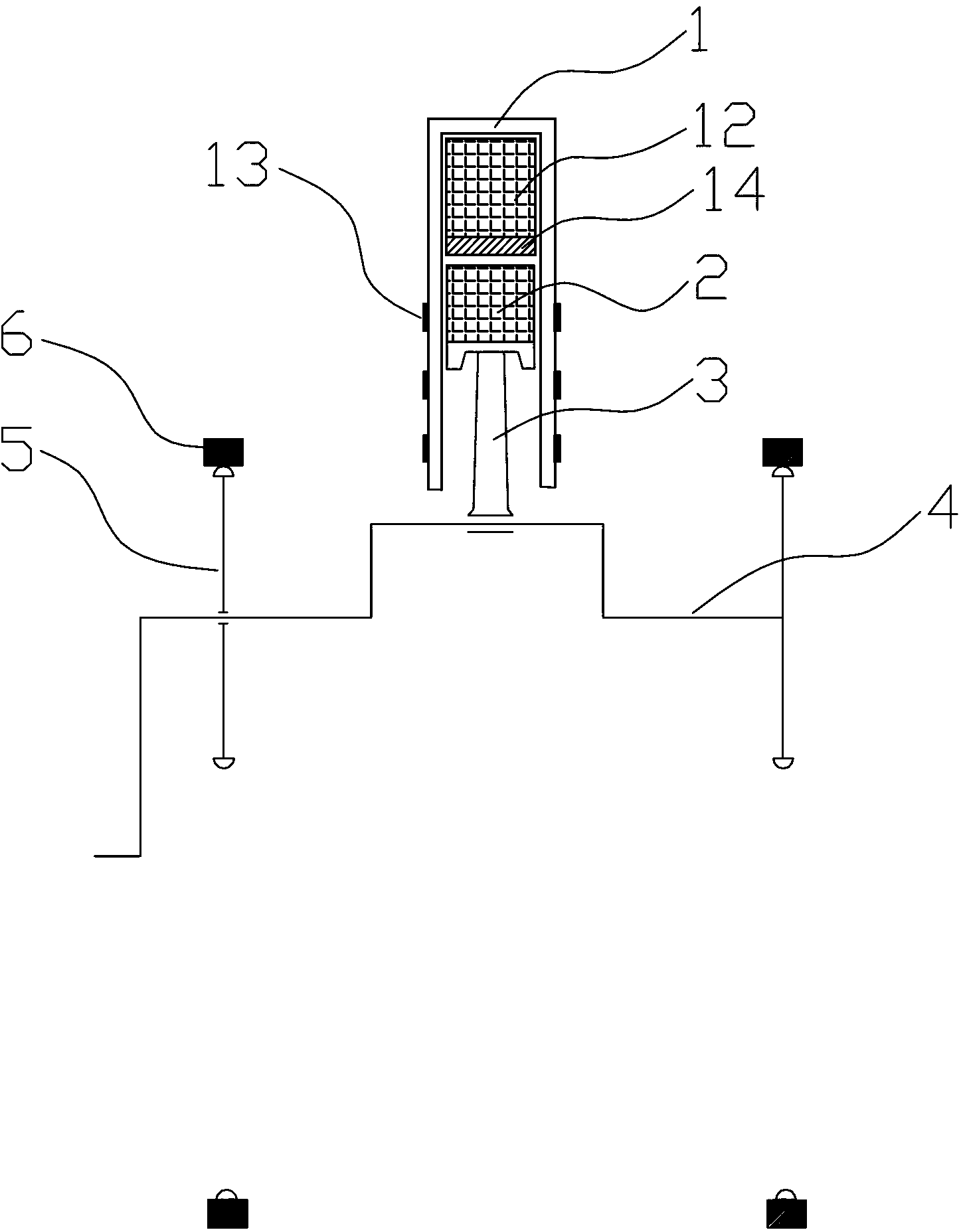
[0030] Examples, see figure 1 , the magnetoelectric hybrid continuous drive method provided by the invention, it comprises the following steps:

[0031] (1) Prepare the connecting rod 3, the piston and the crankshaft 4, and fix the piston permanent magnet 2 on the top of the piston. One end of the connecting rod 3 is fixedly connected with the piston, and the angle between the connecting rod 3 and the piston does not change. The other end is movably connected with crankshaft 4;

[0032] (2) Prepare the cylinder 1, the cylinder 1 is provided with at least one cylinder, the cylinder permanent magnet 12 is fixed on the top of the cylinder, the piston is inserted in the cylinder, and the cylinder permanent magnet 12 The generated magnetic field force is repelled by the magnetic field force generated by the piston permanent magnet 2; the pole-changing coil 14 is fixedly arranged at the bottom of the cylinder permanent magnet 12; multiple groups of drive coils 13 are arranged at eq...


PUM


Abstract

The invention discloses a magnetic electricity mixed continuous driving method. The magnetic electricity mixed continuous driving method comprises the following steps: (1) a connection rod, a piston and a crank shaft are prepared; (2) a cylinder body, a pole changing coil and a drive coil are prepared;(3) a control system is prepared; (4) in an original state, the pole changing coil is power-off; (5) the pole changing coil is power-on, and the piston drives the connection rod to move; (6) a first drive coil is power-on, and the piston moves; a current of the first drive coil flows reversely, and the piston moves; (7) a second drive coil is power-on, and the piston moves; the first drive coil is power-off, the step (6) is repeated, and a third drive coil and an n drive coil are power-on and power-off in sequence; (8) the control system controls the current direction of the pole changing coil to enable the current to flow, and actions of the step (6) and the step (7) are repeated; (9) actions of the steps (5), (6), (7) and (8) are repeated, and driving methods of magnetic electricity mixed continuous driving and output motive power driving are achieved. The invention further discloses a motive power device of the magnetic electricity mixed continuous driving.

Description

technical field [0001] The invention relates to the technical field of magnets, magnetoelectric hybrid technology and a power device, in particular to a magnetoelectric hybrid continuous driving method and a power device. Background technique [0002] At present, various prime movers such as gasoline engines, diesel engines, and fuel steam engines have been widely used in many fields such as industry, agriculture, transportation, and national defense. Hidden danger: some of these equipments have huge investment, some consume a lot of fuel, and waste emissions, noise, etc. pollute the environment seriously. Moreover, the energy used by the above-mentioned engines is non-renewable resources such as coal, oil, etc. Due to limited resources, energy consumption has been paid more and more attention by people, and its energy conversion process is complex, costly, low in efficiency, and seriously pollutes the environment. . [0003] At present, there is no power machine on the ma...

Claims


Application Information

Patent Timeline
Patent Type & Authority Applications(China)
IPC IPC(8): H02K7/06
Inventor 罗琨
Owner 罗琨
Learn More