Signal measurement method

A signal and amplified signal technology, applied in the field of analog circuit design, can solve the difficulties and complexity of filter implementation, and achieve the effect of increasing complexity, easy operation and amplifier, and reducing ripple amplitude

Active Publication Date: 2015-08-19
苏州唯理创新科技有限公司
View PDF3 Cites 0 Cited by
  • Summary
  • Abstract
  • Description
  • Claims
  • Application Information

AI Technical Summary

Problems solved by technology

Filters that meet this requirement are difficult and complex to implement

Method used


Image

  • Signal measurement method
  • Signal measurement method
  • Signal measurement method

Examples


Embodiment Construction

[0034] The embodiments of the circuit for reducing the output ripple of the chopper amplifier will be described in detail below in conjunction with the accompanying drawings. It should be emphasized that the following description is only exemplary and not intended to limit the scope of the invention and its application.

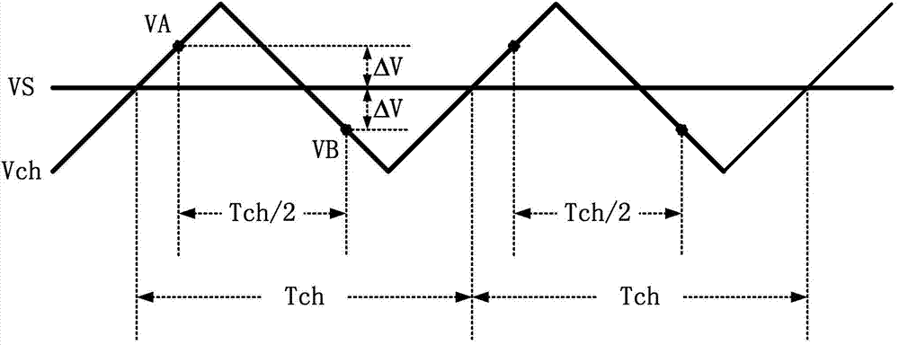
[0035] image 3 is a schematic diagram of the output signal of the chopper amplifier and the ripple signal superimposed on it. VS in the figure represents the output signal, Vch in the shape of a triangular wave represents the ripple signal remaining at the output end of the amplifier, and its frequency is expressed as fch. Since the frequency fch of the chopping signal is much higher than the frequency of the output signal, the output signal VS is basically unchanged within a chopping cycle Tch, while the ripple signal Vch is symmetrically distributed up and down relative to the output signal VS. According to this feature, the total signal including the ou...


PUM


Abstract

The invention discloses a circuit for reducing chopping amplifier output ripple. The circuit comprises a switching capacitor sampling summing circuit, wherein the switching capacitor sampling summing circuit comprises a first switching capacitor circuit, a second switching capacitor circuit and a summing circuit, the second switching capacitor circuit and the first switching capacitor circuit are connected in parallel and have the same structure, and output ends of the first switching capacitor circuit and the second switching capacitor circuit are connected to the input end of the summing circuit. The invention also discloses a measuring device and an amplifying signal measuring method. The circuit for reducing chopping amplifier output ripple is used. The chopping amplifier output ripple width is reduced, an analog low-pass filter is not required, the energy consumption and the area are saved and the design of the circuit is simplified.

Description

technical field [0001] The invention belongs to the field of analog circuit design, in particular to a circuit for reducing the output ripple of a chopper amplifier, a measuring device and a method for measuring an amplified signal. Background technique [0002] The instrumentation amplifier can amplify weak signals. It is a high-performance analog circuit that operates at low frequency, has low noise and low offset, and has a wide range of applications. In order to reduce the interference of the amplifier's own offset voltage and low-frequency noise to the input signal, the input signal can usually be modulated to a high frequency by chopping, and the low-frequency interference signal of the amplifier is separated in the frequency domain, and the input signal is amplified and then modulated At the same time, low-frequency interfering signals are modulated to high frequencies, thereby improving the accuracy with which the amplifier can handle signals. [0003] However, in s...

Claims


Application Information

Patent Timeline
Patent Type & Authority Patents(China)
IPC IPC(8): H03F3/187H03F1/02
Inventor 姜珲王自强张春麦宋平陈虹姜汉钧王志华
Owner 苏州唯理创新科技有限公司
Why Eureka
Try Eureka