Diagnosis assistance system and program

A support system and area technology, applied in the field of diagnosis support system and program, can solve problems such as difficult to grasp symptoms

Active Publication Date: 2013-04-24
KONICA MINOLTA MEDICAL & GRAPHICS INC
View PDF7 Cites 6 Cited by
  • Summary
  • Abstract
  • Description
  • Claims
  • Application Information

AI Technical Summary

Problems solved by technology

[0006] On the other hand, in the technology of Patent Document 1, only the maximum value of the inter-frame difference value of each pixel o

Method used


Image

  • Diagnosis assistance system and program
  • Diagnosis assistance system and program
  • Diagnosis assistance system and program

Examples


no. 1 Embodiment approach 〉

[0058] [Configuration of Diagnosis Support System 100 ]

[0059] First, the configuration will be described.

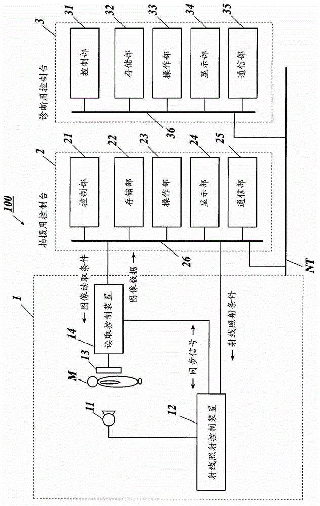
[0060] figure 1 The overall configuration of the diagnosis support system 100 in this embodiment is shown.

[0061] Such as figure 1 As shown, the diagnostic support system 100 is configured such that the imaging device 1 and the imaging console 2 are connected via a communication cable or the like, and the imaging console 2 and the diagnostic console 3 are connected via a communication network NT such as a LAN (Local Area Network). . Each device constituting the diagnosis support system 100 complies with the DICOM (Digital Image and Communications in Medicine: Digital Image and Communications in Medicine) standard, and communication between the devices is performed in compliance with DICOM.

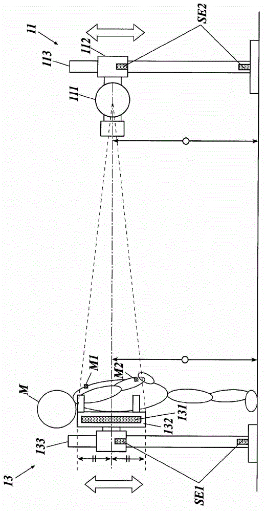
[0062] [Configuration of Imaging Device 1 ]

[0063] The imaging device 1 is, for example, a device that captures periodic (periodic) movements of the chest such as expansi...

no. 2 Embodiment approach 〉

[0211] Next, a second embodiment of the present invention will be described. In the second embodiment, in Figure 4 The content of the image analysis / display process executed in step S12 is different from that of the first embodiment, so the image analysis / display process (image analysis / display process B) of the second embodiment will be described below.

[0212] Figure 20 expressed in Figure 4 A flowchart of the image analysis / display process B executed by the control unit 31 in step S12 of . The image analysis / display process B is executed by cooperation of the control unit 31 and the program stored in the storage unit 32 .


PUM


Abstract

Provided is a GUI-containing system that effectively utilizes kymographic images, integrates information to be used for diagnosis in a viewing system and allows accurate diagnosis even by physicians who have little experience with stethoscopes. With this diagnosis assistance system (100), a control unit (31) of a diagnostic console (3) extracts the lung field regions from the respective image frames of a plurality of image frames representing the movements of the chest, which have been transmitted from an imaging console (2); divides said extracted lung field regions into a plurality of sub-regions; correlates the divided sub-regions in the plurality of image frames with each other and analyses same; thereby calculating previously established characteristic quantities that represent the movement of the divided sub-regions. When the regions for display of analysis results are selected by the operating unit (33), the characteristic quantities for the selected sub-regions are displayed.

Description

technical field [0001] The present invention relates to a diagnosis support system and a program. Background technique [0002] Traditionally, doctors have comprehensively performed lung ventilation functions using image information from chest X-rays (images taken when the lung field area is the largest during deep breathing) and sound information from a stethoscope. diagnosis. [0003] In contrast, in recent years, attempts have been made to capture dynamic images of the chest using semiconductor image sensors such as FPDs (flat panel detectors) and to apply them to diagnosis. For example, Patent Document 1 describes a technique of generating a difference image representing a difference in signal value between a plurality of frame images constituting a moving image, and obtaining the maximum value of each signal value from the generated difference image. technology for display. [0004] Patent Document 1: Japanese Unexamined Patent Publication No. 2004-312434 [0005] H...

Claims


Application Information

Patent Timeline
IPC IPC(8): A61B6/00
CPCA61B6/469A61B6/463G06T2207/10016A61B6/507A61B6/5217A61B5/087G06T2207/10116G06T2207/30104G06K9/3241A61B6/50G06T2207/20021A61B5/026G06T7/00G06T7/0016G06T2200/24G06T2207/30061G16H50/30G06T7/0012
Inventor 村冈慎太郎野地翔岛田哲雄
Owner KONICA MINOLTA MEDICAL & GRAPHICS INC
Why Eureka
Try Eureka