Direct current power supply device

A technology of DC power supply and power supply unit, applied in the direction of output power conversion devices, circuits, discharge tubes, etc., can solve problems such as arc discharge, low impedance, excessive reverse current, etc., and achieve the best effect of arc suppression treatment

Active Publication Date: 2013-04-24
ULVAC INC
View PDF8 Cites 5 Cited by
  • Summary
  • Abstract
  • Description
  • Claims
  • Application Information

AI Technical Summary

Problems solved by technology

However, even if a positive voltage is generated like this, if the impedance is very low when arcing occurs, an excessive reverse current will be generated, and since a positive voltage that is more than 10% higher than the negative voltage specified by the process is applied, the inside of the vacuum device The anode and cathode of the switch, sometimes become the reverse sputtering state, there is a problem that the arc discharge is easy to occur again when the arc discharge continues or when the power is applied to the target again after recovering from the arc treatment
[0007] In addition, it is also proposed that when arcing occurs, a resistor is placed in series on the circuit where the positive voltage is applied, but this will reduce the ability to extinguish the arcing, and it is also impossible to apply a positive voltage of more than 10%.

Method used


Image

  • Direct current power supply device
  • Direct current power supply device
  • Direct current power supply device

Examples


Embodiment Construction

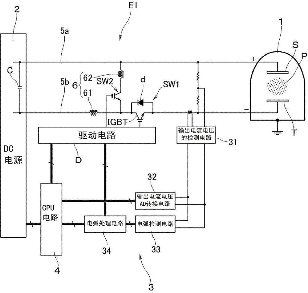
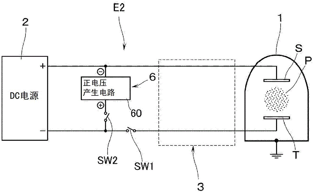
[0037] Referring to the following drawings, DC power supply devices E1 and E2 according to the embodiment of the present invention will be described by taking a case where a DC power is applied to a target by a sputtering apparatus as an example.

[0038] Such as figure 1 As shown, the DC power supply device E1 is arranged opposite to the substrate S arranged in the processing chamber 1 of the sputtering apparatus, for example, and is a device that applies DC power to the target T that is an electrode contacting the plasma load P. The DC power supply unit E1 has a DC power supply unit 2 capable of supplying DC power, an arc detection unit 3 , and a CPU circuit 4 as a control unit for collectively controlling the operation of the DC power supply unit E1 . Although not particularly shown in the figure, the DC power supply unit 2 inputs commercial AC power (for example, single-phase AC200V, three-phase AC200, etc.), rectifies the input AC power into DC power, and converts it into...


PUM


Abstract

Provided is a direct current power supply device, with which it is possible to apply a positive voltage and eliminate arc discharge, and to reliably suppress recurrences of arc discharge after said elimination thereof when normal operation is restored. The direct current power supply device comprises: a direct current power supply unit that injects electricity into a target; an arc sensor unit; a first switching element (SW1) disposed in series with the negative output; a second switching element (SW2) and an inverse voltage application unit that applies inverse voltage, which are disposed in parallel between the positive and negative outputs; and a control means (4). During normal operation, electricity is transmitted by the first switching element to the electrodes in a state wherein the application of inverse voltage from the inverse voltage application unit to the electrodes is interrupted by the second switching element. If an arc discharge is detected, inverse voltage electricity is transmitted to the electrodes by the second switching element from the inverse voltage application unit and applied over a prescribed interval. After said interval has elapsed, the transmission of electricity to the electrodes is cut off by the first switching element for a prescribed interval. The transmission of electricity to the electrodes recommences thereafter.

Description

technical field [0001] The present invention relates to a DC power supply device for applying power to electrodes contacting a plasma load, in particular for use in a sputtering (hereinafter "sputtering") device. Background technique [0002] As a method of forming a film on the surface of a substrate such as glass or a silicon wafer, it is conventionally known to use a sputtering apparatus. In this sputtering device, for example, a predetermined sputtering gas (argon gas) is introduced into a processing chamber under a vacuum atmosphere, and a direct current power supply device is used to produce a component corresponding to a thin film to be formed on the substrate surface as a contact plasma load. The electrodes of the target apply electric power to form a plasma atmosphere. In addition, the ions in the plasma atmosphere are accelerated and collided with the target, and the sputtered particles (target atoms) are scattered and deposited on the surface of the substrate to ...

Claims


Application Information

Patent Timeline
Patent Type & Authority Applications(China)
IPC IPC(8): H05H1/46C23C14/34H05H1/00H02M3/155
CPCH01J37/32944H05H2001/4682H02M3/158H05H1/46H05H2242/22C23C14/34H05H1/00H02M3/155
Inventor 堀下芳邦松原忍小野敦
Owner ULVAC INC
Why Eureka
Try Eureka